This post is older than 2 years and might not be relevant anymore
More Info: Consider searching for newer posts

How to use EasyDMA as an event for PPI?

I combined the BLE UART and SPIS Peripheral example of SDK V17.0.2 to receive data from a microcontroller using SPIS protocol in every 32 milliseconds and send it over through BLE at 128 milliseconds intervals. However, the EasyDMA is turned on all the time (see the main loop in the attached code) and thus the nRF52832 is consuming around 2mA current all the time.

So, to reduce current consumption, I want to enable EasyDMA only when the SPIS transfer is occurring i.e., 32 milliseconds. Thus, I am planning to use PPI and GPIOTE to sense chip select (CS) pin and use it as an Event and enable EasyDMA as the Task. 

However, as I went through the documentation, I could not find any reference on how to get the task endpoint address for EasyDMA. I need that address to configure the PPI.

Please let me know how can I get the EasyDMA task endpoint address or any other way to enable EasyDMA only for 32 milliseconds

int main(void)
{
    bool erase_bonds;
    
    // Initialize.
    log_init();
    timers_init();
    power_management_init();
    ble_stack_init();
    gap_params_init();
    gatt_init();
    services_init();
    advertising_init();
    conn_params_init();

    // Start execution.
    NRF_LOG_INFO("Debug logging for UART over RTT started.");
    advertising_start();
    
    conn_evt_len_ext_set(true);

    uint32_t       err_code;
    //SPI Initialization
    NRF_LOG_INFO("SPIS example");
    nrf_drv_spis_config_t spis_config = NRF_DRV_SPIS_DEFAULT_CONFIG;
    spis_config.csn_pin               = APP_SPIS_CS_PIN;
    spis_config.miso_pin              = APP_SPIS_MISO_PIN;
    spis_config.mosi_pin              = APP_SPIS_MOSI_PIN;
    spis_config.sck_pin               = APP_SPIS_SCK_PIN;

    APP_ERROR_CHECK(nrf_drv_spis_init(&spis, &spis_config, spis_event_handler));

    // Enter main loop.
    for (;;)
    {
      // Reset rx buffer and transfer done flag
        if (master_connected == true) //Start SPIS receive only when master is connected
        {
            memset(m_rx_buf, 0, m_length);
            spis_xfer_done = false;

            APP_ERROR_CHECK(nrf_drv_spis_buffers_set(&spis, connected_buf, m_length_connected, m_rx_buf, m_length));
     
            connected_buf[m_length] = 1; //connected_buf is used to send data to the SPI master
            while (!spis_xfer_done)
            {
                __WFE();
            }
            //__NOP();
        }
        else
        {
            connected_buf[m_length] = 0; //connected_buf is used to send data to the SPI master
        }
        //NRF_LOG_INFO("idle state started.");
        idle_state_handle();
    }
}

Parents
  • Hello , sorry for the delay. I was testing the chip a bit more. One thing I figured out was that the chip was not going to sleep as some log process was active. I disabled the log and now the chip consumes only around 16uA when advertising only. 

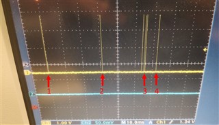
    However, when the SPIS is on, it is consuming around 900uA. To see the SPIS duty cycle, I cleared a GPIO pin before __WFE() (line 46 in the code of the main post) and set a GPIO pin after WFE (line 48). You can see in the attached image that 1, 2, and 4 are prominent 'WFE on' peak that was initialized in every 32ms as I said earlier in the main post. However, in 3, there are some extra peaks that should not be there. Please keep in mind that in this code I combined the BLE UART example and SPIS peripheral example but no data was sent over BLE. Also, I disabled all UART and button functions to mitigate the possibility of pin leakage.  

    Also, I included power management code in the SPIS peripheral example in the SDK and traced the WFE. There are no extra peaks between the prominent WFE peaks in 32ms. Also, the current consumption is around 480uA.  

     So, I think the extra peaks (WFE on time) are responsible for the extra (900-480) or, 520uA current consumption. What steps should I take to debug those extra 'WFE on' peaks?

  • Hi,


    Rafi said:

    However, when the SPIS is on, it is consuming around 900uA. To see the SPIS duty cycle, I cleared a GPIO pin before __WFE() (line 46 in the code of the main post) and set a GPIO pin after WFE (line 48). You can see in the attached image that 1, 2, and 4 are prominent 'WFE on' peak that was initialized in every 32ms as I said earlier in the main post. However, in 3, there are some extra peaks that should not be there. Please keep in mind that in this code I combined the BLE UART example and SPIS peripheral example but no data was sent over BLE. Also, I disabled all UART and button functions to mitigate the possibility of pin leakage.  

    Also, I included power management code in the SPIS peripheral example in the SDK and traced the WFE. There are no extra peaks between the prominent WFE peaks in 32ms. Also, the current consumption is around 480uA.  

    If you use WFE directly with the softdevice, you will also be awoken by the softdevice events, so you will get spikes when the bluetooth link is to be handled. You should use idle_state_handle() function to avoid the application being awoken by softdevice interrupts.

    Unless the softdevice is completely inactive, you cannot guarantee that those spikes aren't from outside the application scope.


    Have you scoped the SPI pins to ensure that everything looks according to the SPI mode that you have configured? If CSN is active, the clock source will also be active, which will draw more current.


    Kind regards,

    Håkon

Reply
  • Hi,


    Rafi said:

    However, when the SPIS is on, it is consuming around 900uA. To see the SPIS duty cycle, I cleared a GPIO pin before __WFE() (line 46 in the code of the main post) and set a GPIO pin after WFE (line 48). You can see in the attached image that 1, 2, and 4 are prominent 'WFE on' peak that was initialized in every 32ms as I said earlier in the main post. However, in 3, there are some extra peaks that should not be there. Please keep in mind that in this code I combined the BLE UART example and SPIS peripheral example but no data was sent over BLE. Also, I disabled all UART and button functions to mitigate the possibility of pin leakage.  

    Also, I included power management code in the SPIS peripheral example in the SDK and traced the WFE. There are no extra peaks between the prominent WFE peaks in 32ms. Also, the current consumption is around 480uA.  

    If you use WFE directly with the softdevice, you will also be awoken by the softdevice events, so you will get spikes when the bluetooth link is to be handled. You should use idle_state_handle() function to avoid the application being awoken by softdevice interrupts.

    Unless the softdevice is completely inactive, you cannot guarantee that those spikes aren't from outside the application scope.


    Have you scoped the SPI pins to ensure that everything looks according to the SPI mode that you have configured? If CSN is active, the clock source will also be active, which will draw more current.


    Kind regards,

    Håkon

Children
No Data
Related