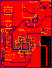
This post is older than 2 years and might not be relevant anymore
More Info: Consider searching for newer posts

Verification for schematic for custom Board

Hi,

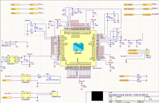
We are design custom Board using nRF52840 SOC.

  1. We are operating it in Normal mode, using internal DCDC converter
  2. We have used configuration 5 from reference design
  3. From reference design we have removed NFC pins connection and USB connection because we do not need it in our design
  4. We will be programing our custom board using nRF52840 DK
  5. We have attach led using load switch at P0.15
  6. We have attach buzzer using load switch at P0.16
  7. We have attach button at P0.24
  8. We have taken antenna schematic from nRF52840DK hardware files and remove external connector. Have we done it correctly?
  9. Have we connected reset button correctly?

I am attaching the Schematic design for our board can you verify it if it is correct or we are missing something, If it is unclear in picture I can also attach schematic file

Thanks in advance
Regards,

Moghees Bin Zahid

Parents
  • Hi Moghees,

    Thanks for the detailed information.

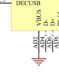
    When not using USB you can ground VBUS as seen in circuit configuration no. 6:

    We have taken antenna schematic from nRF52840DK hardware files and remove external connector. Have we done it correctly?

    Yes, but whether or not you only need antenna matching component C23 depends on what type of antenna you are planning on using. If you are copying the antenna layout from the nRF52840 DK, then one antenna matching component will probably work fine, otherwise we'd recommend a pi-network of antenna matching components for greater versatility in tuning the antenna.

    The reset button is connected correctly.

    What's just as critical is the PCB layout, so feel free to share that when you have it done and we can take a look at it.
    If you follow the reference layout exactly you shouldn't have any issues.

    Best regards,

    Martin S.

  • Thanks for the reply Martin. Firstly I want to appreciate the documentation of Nordic.  

    Yes, but whether or not you only need antenna matching component C23 depends on what type of antenna you are planning on using. If you are copying the antenna layout from the nRF52840 DK, then one antenna matching component will probably work fine, otherwise we'd recommend a pi-network of antenna matching components for greater versatility in tuning the antenna.

    I will be using same Antenna used in nRF52840DK. I want to ask can I copy antenna for nRF52840DK PCB layout and placed it on my PCB layout? If yes then in place of connector that is connected for external antenna of DK I should just extend antenna layout?

    I have few others questions:
    1. Can I remove net names and wires that I am not using in our design?

    2. It is first time I am designing PCB using nRF52840 SoC. Can you recommend me document that I can follow?

    3. Can I use reference layout PCB layout and extend it for our PCB?


    Regards,
    Moghees Bin Zahid

  • Hi Martin,
    I have selected all the components after seeing the specification given in Altium Hardware files. I am attaching BOM containing a link to the components I am using. If it is possible can you verify capacitors, inductors, and oscillators are of correct specification

    BOM_LL_v0.2.0.xlsx

    Regards,
    Moghees Bin Zahid
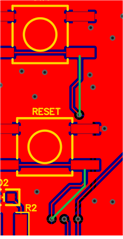
  • Hi Moghees,

    The BOM looks fine. You can remove C22 from the BOM since you've removed it from the design. The 32 MHz crystal is in a smaller package than what we use (we use 2016, 2.0 x 1.6 mm), but it should work as well.

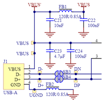
    Adding C21, FB1, C22 and FB2 to the USB connector is a good idea.

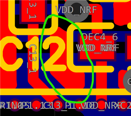
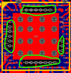
    I still see some unused traces that are not removed:

    Here is also an "island" of copper that you should remove:

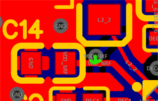
    You can remove the vias marked in green as they are not needed anymore:

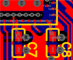
    Move the via directly down so it sits in the middle of the red trace as well:

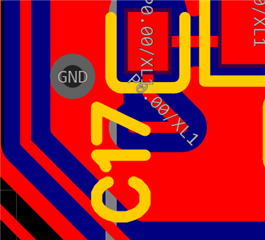
    Move the via out from the pad:

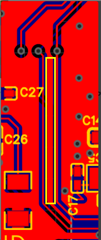
    Here you have a long piece of copper that will become an antenna, remove it:

    I still see a lot of meandering traces that could be straightened out:

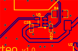
    If you rotate U5 180 degrees it should be easier to connect the traces to it:

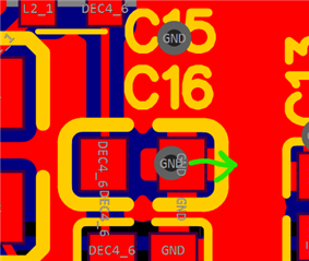
    Add more vias (my suggestions in green):

    Best regards,

    Martin S.

  • Hi Martin,
    Thank you for the detailed reply. I am sorry for causing you any inconvenience. I will get these changes done and get back to you.

    Regards,
    Moghees Bin Zahid
  • All points are clear just to confirm one point

    Here you have a long piece of copper that will become an antenna, remove it:

    you were pointing to remove the part highlighted in yellow box, as shown in the below image?

Reply Children
Related