Hello.
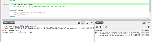
I get an error NRF_BREAKPOINT_COND. I use nRF5_SDK_17.0.2, s132_nrf52_7.2.0_softdevice and my kit - nRF52-DK.
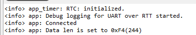
An error occurs when trying to swap UART pins (Change RX_PIN_NUMBER 3 (8) and TX_PIN_NUMBER 4 (6) ) in example nRF5_SDK_17.0.2_d674dde \ examples \ ble_peripheral \ ble_app_uart:
#define PCA10040_H
#ifdef __cplusplus
extern "C" {
#endif
#include "nrf_gpio.h"
// LEDs definitions for PCA10040
#define LEDS_NUMBER 4
#define LED_START 17
#define LED_1 17
#define LED_2 18
#define LED_3 19
#define LED_4 20
#define LED_STOP 20
#define LEDS_ACTIVE_STATE 0
#define LEDS_INV_MASK LEDS_MASK
#define LEDS_LIST { LED_1, LED_2, LED_3, LED_4 }
#define BSP_LED_0 LED_1
#define BSP_LED_1 LED_2
#define BSP_LED_2 LED_3
#define BSP_LED_3 LED_4
#define BUTTONS_NUMBER 4
#define BUTTON_START 13
#define BUTTON_1 13
#define BUTTON_2 14
#define BUTTON_3 15
#define BUTTON_4 16
#define BUTTON_STOP 16
#define BUTTON_PULL NRF_GPIO_PIN_PULLUP
#define BUTTONS_ACTIVE_STATE 0
#define BUTTONS_LIST { BUTTON_1, BUTTON_2, BUTTON_3, BUTTON_4 }
#define BSP_BUTTON_0 BUTTON_1
#define BSP_BUTTON_1 BUTTON_2
#define BSP_BUTTON_2 BUTTON_3
#define BSP_BUTTON_3 BUTTON_4
#define RX_PIN_NUMBER 3
#define TX_PIN_NUMBER 4
#define CTS_PIN_NUMBER 7
#define RTS_PIN_NUMBER 5
#define HWFC true
//#define SPIS_MISO_PIN 28 // SPI MISO signal.
//#define SPIS_CSN_PIN 12 // SPI CSN signal.
//#define SPIS_MOSI_PIN 25 // SPI MOSI signal.
//#define SPIS_SCK_PIN 29 // SPI SCK signal.
//#define SPIM0_SCK_PIN 29 // SPI clock GPIO pin number.
//#define SPIM0_MOSI_PIN 25 // SPI Master Out Slave In GPIO pin number.
//#define SPIM0_MISO_PIN 28 // SPI Master In Slave Out GPIO pin number.
//#define SPIM0_SS_PIN 12 // SPI Slave Select GPIO pin number.
//#define SPIM1_SCK_PIN 2 // SPI clock GPIO pin number.
//#define SPIM1_MOSI_PIN 3 // SPI Master Out Slave In GPIO pin number.
//#define SPIM1_MISO_PIN 4 // SPI Master In Slave Out GPIO pin number.
//#define SPIM1_SS_PIN 5 // SPI Slave Select GPIO pin number.
//#define SPIM2_SCK_PIN 12 // SPI clock GPIO pin number.
//#define SPIM2_MOSI_PIN 13 // SPI Master Out Slave In GPIO pin number.
//#define SPIM2_MISO_PIN 14 // SPI Master In Slave Out GPIO pin number.
//#define SPIM2_SS_PIN 15 // SPI Slave Select GPIO pin number.
//// serialization APPLICATION board - temp. setup for running serialized MEMU tests
//#define SER_APP_RX_PIN 23 // UART RX pin number.
//#define SER_APP_TX_PIN 24 // UART TX pin number.
//#define SER_APP_CTS_PIN 2 // UART Clear To Send pin number.
//#define SER_APP_RTS_PIN 25 // UART Request To Send pin number.
//#define SER_APP_SPIM0_SCK_PIN 27 // SPI clock GPIO pin number.
//#define SER_APP_SPIM0_MOSI_PIN 2 // SPI Master Out Slave In GPIO pin number
//#define SER_APP_SPIM0_MISO_PIN 26 // SPI Master In Slave Out GPIO pin number
//#define SER_APP_SPIM0_SS_PIN 23 // SPI Slave Select GPIO pin number
//#define SER_APP_SPIM0_RDY_PIN 25 // SPI READY GPIO pin number
//#define SER_APP_SPIM0_REQ_PIN 24 // SPI REQUEST GPIO pin number
//// serialization CONNECTIVITY board
//#define SER_CON_RX_PIN 24 // UART RX pin number.
//#define SER_CON_TX_PIN 23 // UART TX pin number.
//#define SER_CON_CTS_PIN 25 // UART Clear To Send pin number. Not used if HWFC is set to false.
//#define SER_CON_RTS_PIN 2 // UART Request To Send pin number. Not used if HWFC is set to false.
//#define SER_CON_SPIS_SCK_PIN 27 // SPI SCK signal.
//#define SER_CON_SPIS_MOSI_PIN 2 // SPI MOSI signal.
//#define SER_CON_SPIS_MISO_PIN 26 // SPI MISO signal.
//#define SER_CON_SPIS_CSN_PIN 23 // SPI CSN signal.
//#define SER_CON_SPIS_RDY_PIN 25 // SPI READY GPIO pin number.
//#define SER_CON_SPIS_REQ_PIN 24 // SPI REQUEST GPIO pin number.
//#define SER_CONN_CHIP_RESET_PIN 11 // Pin used to reset connectivity chip
//// Arduino board mappings
//#define ARDUINO_SCL_PIN 27 // SCL signal pin
//#define ARDUINO_SDA_PIN 26 // SDA signal pin
//#define ARDUINO_AREF_PIN 2 // Aref pin
//#define ARDUINO_13_PIN 25 // Digital pin 13
//#define ARDUINO_12_PIN 24 // Digital pin 12
//#define ARDUINO_11_PIN 23 // Digital pin 11
//#define ARDUINO_10_PIN 22 // Digital pin 10
//#define ARDUINO_9_PIN 20 // Digital pin 9
//#define ARDUINO_8_PIN 19 // Digital pin 8
//#define ARDUINO_7_PIN 18 // Digital pin 7
//#define ARDUINO_6_PIN 17 // Digital pin 6
//#define ARDUINO_5_PIN 16 // Digital pin 5
//#define ARDUINO_4_PIN 15 // Digital pin 4
//#define ARDUINO_3_PIN 14 // Digital pin 3
//#define ARDUINO_2_PIN 13 // Digital pin 2
//#define ARDUINO_1_PIN 12 // Digital pin 1
//#define ARDUINO_0_PIN 11 // Digital pin 0
//#define ARDUINO_A0_PIN 3 // Analog channel 0
//#define ARDUINO_A1_PIN 4 // Analog channel 1
//#define ARDUINO_A2_PIN 28 // Analog channel 2
//#define ARDUINO_A3_PIN 29 // Analog channel 3
//#define ARDUINO_A4_PIN 30 // Analog channel 4
//#define ARDUINO_A5_PIN 31 // Analog channel 5
#ifdef __cplusplus
}
#endif
#endif // PCA10040_H
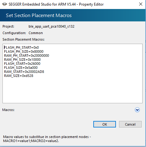
Project memory setting:
What needs to be changed in the project so that the error does not occur?
Thanks.