This post is older than 2 years and might not be relevant anymore
More Info: Consider searching for newer posts

nRF52840 Antenna matching network

Hi

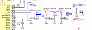
I am usig a nRF52840 with the chip antenna 2450AT18D0100E (Johanson Technology).

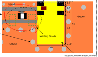
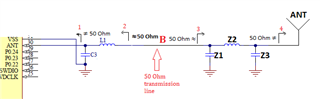
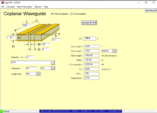
How should I calculate the matching filter? I used the values from the reference design, but the smith chart and return loss diagram are showing some really bad and not matching results for the BLE function.

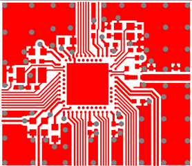
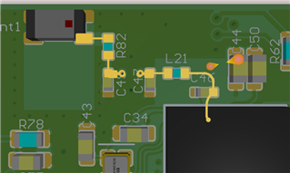
the Altium file is in the zip file

Copy of SmartlinkBle_V3a.zip

Parents
  • Hi Dominik, 

    Best way to figure out the correct matching is to test, you can only get so far with calculating/simulating. When not following the reference layout the result will differ due to stray capacitance and inductance. 

    I do highly recommend that you follow the layout also. 


    Have you made sure that the transmission line is close to 50 Ohm ?


    In the data sheet the chip antenna has a recomendation for layout as well. 


    When it comes to the radio matching components it is important to remember that the the components also serve to filter harmonics. 

    Regards,
    Jonathan


Reply
  • Hi Dominik, 

    Best way to figure out the correct matching is to test, you can only get so far with calculating/simulating. When not following the reference layout the result will differ due to stray capacitance and inductance. 

    I do highly recommend that you follow the layout also. 


    Have you made sure that the transmission line is close to 50 Ohm ?


    In the data sheet the chip antenna has a recomendation for layout as well. 


    When it comes to the radio matching components it is important to remember that the the components also serve to filter harmonics. 

    Regards,
    Jonathan


Children
  • Have you made sure that the transmission line is close to 50 Ohm ?

    Do I need to measure this without antenna only the transmission line? Then add the antenna and tune to 2.4GHz?

  • Hi,

    In this case you can see a reply from Kaja.

    For best tuning of the antenna i would contact the manufacturer to se what they recommend for your use case. We also do tuning of the radio and antenna here at Nordic, but if low pas filters are used, there is not much we can do for the radio. 

    in short:

    The radio matching network and the antenna matching network 

    should be connected with a 50 Ohm coplanar wave guide:

    The length, L, does not matter in theory, but a very long RF path is not optimal, but 15-20 mm is not a problem.


    In your case the distance is short and you have a connector in the middel. The most importen ting is to reduce ground loops and have propper grounding. You dont have to measure this but you can use digital tools to calculate and incorporate it in your design. Altium has such tools.  


    As for chip antennas here is a short summery(link to more detail):

    Chip antenna: Higher BOM, but the antenna is small. The downside is that it usually has less gain. It requires a matching network, based on the vendors recommendations. It has a lower bandwidth than a quarter wave monopole antenna so it can be sensitive to detuning.

    As a rule we do not usually recommend specific chip antennas. The selection will depend very much on the end application design, the antenna vendors can assist on choosing the right antenna for a specific design, for example Johanson has a useful tool that helps with this selection: https://www.johansontechnology.com/chip-antenna-selection


    Regards,
    Jonathan

Related