This post is older than 2 years and might not be relevant anymore
More Info: Consider searching for newer posts

nRF52840 Antenna matching network

Hi

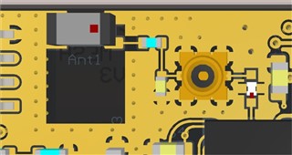
I am usig a nRF52840 with the chip antenna 2450AT18D0100E (Johanson Technology).

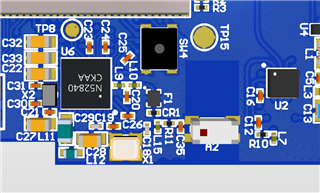
How should I calculate the matching filter? I used the values from the reference design, but the smith chart and return loss diagram are showing some really bad and not matching results for the BLE function.

the Altium file is in the zip file

Copy of SmartlinkBle_V3a.zip

Parents
  • Hi

    Thanks for your answer. I can't follow the layout, beacuse I have another schematic and application.

    The transmission line I can check and adjust to 50 Ohms, I will do this, then maybe it's better.

    Anyway I changed the RF part with a low pass filter 2450FM07B0037. I think this will improve a lot the stability and dB, do you agree?

    Regards, Dominik

  • Dominik Eugster said:
    I can't follow the layout, beacuse I have another schematic and application.

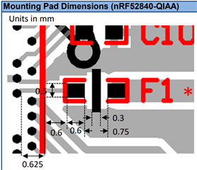
    To get the best possible RF results then i suggest that you try to follow the reference of the RF area as close as possible, even if you cant do it 1:1. 
    Preferably we do recommend that the RF path/transmission line is a grounded coplanar wave guide(GCPW). Adding proper via shielding.  


    Dominik Eugster said:
    Anyway I changed the RF part with a low pass filter 2450FM07B0037. I think this will improve a lot the stability and dB, do you agree?

     The Johanson low pass filter does work but i often find it does have a bit more loss then a vell tuned matching network. Bu make sure you follow the layout exactly to get the desired effect.


    The transmission line should also have a singel ground reference plane. So the layer beneath the signal path for the antenna should be a ground layer. To serve as the RF ground. 

    Regards,
    Jonathan

Reply
  • Dominik Eugster said:
    I can't follow the layout, beacuse I have another schematic and application.

    To get the best possible RF results then i suggest that you try to follow the reference of the RF area as close as possible, even if you cant do it 1:1. 
    Preferably we do recommend that the RF path/transmission line is a grounded coplanar wave guide(GCPW). Adding proper via shielding.  


    Dominik Eugster said:
    Anyway I changed the RF part with a low pass filter 2450FM07B0037. I think this will improve a lot the stability and dB, do you agree?

     The Johanson low pass filter does work but i often find it does have a bit more loss then a vell tuned matching network. Bu make sure you follow the layout exactly to get the desired effect.


    The transmission line should also have a singel ground reference plane. So the layer beneath the signal path for the antenna should be a ground layer. To serve as the RF ground. 

    Regards,
    Jonathan

Children
Related