This post is older than 2 years and might not be relevant anymore
More Info: Consider searching for newer posts

nRF52840 custom PCB Radio not working

Hi

I was using the MESH SDK 5.0.0 Dimming Server Example on nRF52840 DK and Dongle it worked fine so i designed a custom Board according the Designrules of Nordic.

Setting:

PCB is a 4 Layer 1.6mm, both Cristal where mounted (same Types as on the DK Board)
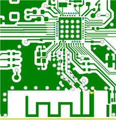
(Backside)

Antenna is an Inverted F Type 
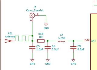
Antenna path

Programmig and powerdelivery is made over the nRF52840dk OS: Win10 with nrf Connect Toolchain 

Faliture:

Device is not transmitting any Bluetooth beacons, App Timer is Running as expected.

RTT is printing no Error ->similar to DK (with different UUID).

Outputs react as expected.

I had checked the following Points:

- Erased the Chip with nrfjprog --recover --Family NRF52 --Log

- HFXTAL on Register 0x4000040C is 00010001 -> 32Mhz Cristal is Up and Working

- LFXTAL on Register 0x40000418 is 00010001 ->32Khz Cristal is Up and Working

- Powersupply external 3.3VDC -> No change

- I tried the same Steps on a second (similar) Board with the same behaviour.

Question:

What could i investigating to resolve the issue.

  • Hi Simsim,

    Dou you have the J3 connecter mounted ? And can you see any activity there?


    You can use the radio_test example to test if there is any activity on the radio.


    We do Schematic and layout reviews so you can submit the full design and we will give some feedback on the nrf related sections. 

    At first glance i don't see anything that would indicate that it would not work. From the pictures you have shared. 

    Regards,
    Jonathan

  • Hi Jonathan

    J3 is mounted but actually i do not have a Scope for the Ghz range.

    I loaded the Radio_test example as you mentioned and did the Test with RSSI sweep  which seems to do what i expect can clearly see the Wave proppagate from CH20 to CH40.

    I also desoldered the R15 Resistor to verify if the Antenna or J3 is the problem. apart of weaker Signal strenge there is no difference.

    I will send you the Schematic and Gerber files private. 

    So i suppose there is something different in the behaviour of the s140 Softdevice in combination with the Hardware.

    Is there any debug CLI for the Softdevice appart from the Errors printed on RTT? 

    Regards

    Simon

  • Hi Simon,

    Simsim said:
    I loaded the Radio_test example as you mentioned and did the Test with RSSI sweep  which seems to do what i expect can clearly see the Wave proppagate from CH20 to CH40.

    This is a good indicator to see that the HW seems to work as expected.  


    Just to double down I would like to see if you could use a BLE sample and you phone to see if it works. 

    Like the BLE blinky, and see if you can see it using the nrf app

    This way we would know it the issue is with MESH software and not the HW. 

    Regards,
    Jonathan

  • Hi Jonathan

    BLE Blinky on nRF52840 Dk runs without any issue

    BLE Blinky on the Customer Board is running(Led, and debugging), but there is no RF activity in RSSI viewer and also not Discoverable by the nrf App(Samsung Galaxy S5,Samsung Galaxy S8Duos , nrf52840 dongle)

    I had set in the radio_test sw the carrier on different channels:

    radio_test CH    RSSI Viewer BLE CH
    0 37 2402Mhz
    20 8
    30 12
    40 17
    50 22
    60 27

     i discovered that the next upper channel also rises when transmitting example Ch12 -64dBm Ch13 -78dBm

    Could there be a problem with the HFCLK 32Mhz Cristal?

    Edit: 20/09/21

    I did some trials with the Dev Board and the Custom board both on channel 30

    Dev Board Custom Board

    Further i Loaded the Zephyr Project "mesh_demo" with the same outcome as with the exampels form the SDK

    Regards

    Simon

  • Hi,

    When using the radio_test you can set the output power to +8dBm to get a bit more juice out, but yes there might be an issue with the 32MHz crystal. I would suggest that you try to load the crystal with a higher load cap value. From 12pF to 16pF might do the trick. 

    You can read about crystal and load caps here: General PCB design guidelines for nRF52 series - Hardware design, test and measurement - nRF5 SDK guides - Nordic DevZone (nordicsemi.com)

    But the you are getting something out of the custom board, witch is good.  

    Regards,
    Jonathan

Related