
Hi,
We are designing a custom Board using nRF52840 SOC.
- We are operating it in Normal mode, using an internal DCDC converter
- We have used configuration 5 from the reference design
- From reference design, we have removed NFC pins connection and USB connection because we do not need it in our design
- We will be programming our custom board using nRF52840 DK
- We have attached the led using load switch at P0.15. Led is ON when the pin is pulled to high logic
- We have attached the buzzer using load switch at P0.06. Buzzer is ON when pin is pulled to the high logic
- We have attached the button at P0.08. Button active state is low i.e, we get low logic at pin when the button is pressed
- We have attached the reset button at pin P0.18/RESET. RESET Button active state is low i.e, we get low logic at pin when the button is pressed
We have evaluated our firmware on nRF52840DK. Now we want to design our custom Board and run our firmware on it. After doing some research on how to use SDK with custom board, we realized we have to add custom_board.h file. We have written custom_board.h file by started with pca10056.h file and removing unused pins. Can you please verify the custom_board.h file, I am attaching it below
2630.custom_board.h
Also tell me if we are missing something else. According to our knowledge inorder to program custom board using nRF52840DK:
1. We need to expose 4 pins on our custom Board SWDIO, SWDCLK, VDD_NRF and GND
2. We also need to add custom_board.h file in components----> boards folder in SDK.
3. We need to run our custom board on 3V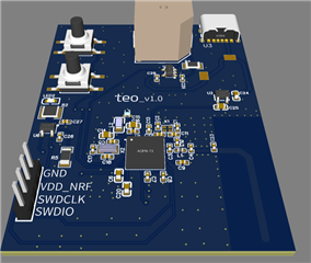
Thanks in advance
Regards,
Moghees Bin Zahid

