
Hey all,
I've been learning/working on the 53 and have had some issues adding in the AMG8 example.
i've gotten the sensor to work flawlessly on an STM32 & nordic 52 but am unable to get it going on zephyr.
My log when running looks like this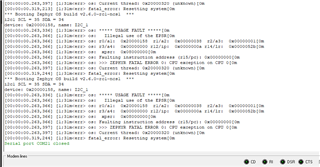
*** Booting Zephyr OS build v2.6.0-rc1-ncs1  ***
i2c1 SCL = 35 SDA = 34
device: 0x20000158, name: I2C_1
[00:00:00.263,336] [1;31m<err> os: ***** USAGE FAULT *****[0m
[00:00:00.263,366] [1;31m<err> os:   Illegal use of the EPSR[0m
[00:00:00.263,366] [1;31m<err> os: r0/a1:  0x20000158  r1/a2:  0x00000038  r2/a3:  0x00000001[0m
[00:00:00.263,366] [1;31m<err> os: r3/a4:  0x00000000 r12/ip:  0x0000000a r14/lr:  0x0000052b[0m
[00:00:00.263,366] [1;31m<err> os:  xpsr:  0x08000000[0m
[00:00:00.263,366] [1;31m<err> os: Faulting instruction address (r15/pc): 0x00000000[0m
[00:00:00.263,397] [1;31m<err> os: >>> ZEPHYR FATAL ERROR 0: CPU exception on CPU 0[0m
[00:00:00.263,397] [1;31m<err> os: Current thread: 0x20000320 (unknown)[0m
[00:00:00.319,244] [1;31m<err> fatal_error: Resetting system[0m
/*
 * Copyright (c) 2017 PHYTEC Messtechnik GmbH
 *
 * SPDX-License-Identifier: Apache-2.0
 */

#include <zephyr.h>
#include <device.h>
#include <drivers/sensor.h>
#include <sys/printk.h>

////NOTE added
#include <devicetree.h>
#include <drivers/gpio.h>


#include <drivers/i2c.h>
#include <dt-bindings/i2c/i2c.h>
#include <nrfx_twim.h>
#include <sys/util.h>

#define Amg88xx_i2c DT_NODELABEL(i2c1)
static struct sensor_value temp_value[64];

#define READERBUFFER_SIZE 5
#define WRITERBUFFER_SIZE 6

uint8_t* readerBuffer = (uint8_t*)0x20000000;
uint8_t* writerBuffer = (uint8_t*)0x20000005;
//uint8_t readerBuffer[READERBUFFER_SIZE] __at__ 0x20000000;
//uint8_t writerBuffer[WRITERBUFFER_SIZE] __at__ 0x20000005;


#ifdef CONFIG_AMG88XX_TRIGGER
K_SEM_DEFINE(sem, 0, 1);

static void trigger_handler(const struct device *dev,
			    struct sensor_trigger *trigger)
{
	ARG_UNUSED(dev);
	ARG_UNUSED(trigger);

	k_sem_give(&sem);
}
#endif


void print_buffer(void *ptr, size_t l)
{
	struct sensor_value *tv = ptr;
	int ln = 0;

	printk("---|");
	for (int i = 0; i < 8; i++) {
		printk("  %02d  ", i);
	}
	printk("\n");

	printk("%03d|", ln);
	for (int i = 0; i < l; i++) {
		printk("%05d ", (tv[i].val1 * 100 + tv[i].val2 / 10000));
		if (!((i + 1) % 8)) {
			printk("\n");
			ln++;
			printk("%03d|", ln);
		}
	}
	printk("\n");
}

uint32_t twim_conf_reg;
uint32_t twim_conf_reg1;
void main(void)
{

	int ret;
	 //const struct device *dev = device_get_binding(DT_LABEL(DT_INST(0, AMG88XX)));
        const struct device *dev =device_get_binding(DT_LABEL(Amg88xx_i2c));

	if (dev == NULL) {
		printk("Could not get AMG88XX device\n");

		return;
	}


 //        //// Configuring the READER channel
 //NRF_TWIM1->RXD.PTR = READERBUFFER_SIZE;
 //NRF_TWIM1->RXD.PTR = (uint32_t)&readerBuffer;

 ////// Configure the WRITER channel
 //NRF_TWIM1->TXD.MAXCNT = WRITERBUFFER_SIZE;
 //NRF_TWIM1->TXD.PTR = (uint32_t)&writerBuffer;


 //       twim_conf_reg = NRF_TWIM1->RXD.PTR;
 //       printk("i2c1 %x \n" ,twim_conf_reg);

 //       twim_conf_reg = NRF_TWIM1->RXD.PTR;
 //       twim_conf_reg1= NRF_TWIM1->TXD.PTR;
 //       printk("i2c1 rxd %x txd %x \n" ,twim_conf_reg,twim_conf_reg1);

        twim_conf_reg = NRF_TWIM1->PSEL.SCL;
        twim_conf_reg1= NRF_TWIM1->PSEL.SDA;
        printk("i2c1 SCL = %d SDA = %d \n" ,twim_conf_reg,twim_conf_reg1);


        printk("device: %p, name: %s\n", dev, dev->name);

        K_MSEC(300);


#ifdef CONFIG_AMG88XX_TRIGGER
	struct sensor_value attr = {
		.val1 = 27,
		.val2 = 0,
	};

	if (sensor_attr_set(dev, SENSOR_CHAN_AMBIENT_TEMP,
			    SENSOR_ATTR_UPPER_THRESH, &attr)) {
		printk("Could not set threshold\n");
		return;
	}

	struct sensor_trigger trig = {
		.type = SENSOR_TRIG_THRESHOLD,
		.chan = SENSOR_CHAN_AMBIENT_TEMP,
	};

	if (sensor_trigger_set(dev, &trig, trigger_handler)) {
		printk("Could not set trigger\n");
		return;
	}
#endif

	while (42) {
#ifdef CONFIG_AMG88XX_TRIGGER
		printk("Waiting for a threshold event\n");
		k_sem_take(&sem, K_FOREVER);
#endif

		ret = sensor_sample_fetch(dev);
		if (ret) {
			printk("Failed to fetch a sample, %d\n", ret);
			return;
		}

		ret = sensor_channel_get(dev, SENSOR_CHAN_AMBIENT_TEMP,
					 (struct sensor_value *)temp_value);
		if (ret) {
			printk("Failed to get sensor values, %d\n", ret);
			return;
		}

		printk("new sample:\n");
		print_buffer(temp_value, ARRAY_SIZE(temp_value));

		k_sleep(K_MSEC(1000));
	}
}
checking the lines using a saleae logic analyzer have no activity on the bus.
setup:
i2c 1, < 0x9000 0x1000 >;
and
uart0 reg = < 0x8000 0x1000 >;
CMAKE:
cmake_minimum_required(VERSION 3.8.2)

find_package(Zephyr REQUIRED HINTS $ENV{ZEPHYR_BASE})
project(amg88xx)


FILE(GLOB app_sources src/*.c)
target_sources(app PRIVATE src/main.c)
ZEPHYR DTS:
/dts-v1/;

/ {
	#address-cells = < 0x1 >;
	#size-cells = < 0x1 >;
	model = "Nordic NRF5340 DK NRF5340 Application";
	compatible = "nordic,nrf5340-dk-nrf5340-cpuapp";
	chosen {
		zephyr,entropy = &cryptocell;
		zephyr,flash-controller = &flash_controller;
		zephyr,console = &uart0;
		zephyr,shell-uart = &uart0;
		zephyr,uart-mcumgr = &uart0;
		zephyr,bt-mon-uart = &uart0;
		zephyr,bt-c2h-uart = &uart0;
		zephyr,ipc_shm = &sram0_shared;
		zephyr,sram = &sram0_image;
		zephyr,flash = &flash0;
		zephyr,code-partition = &slot0_partition;
		zephyr,sram-secure-partition = &sram0_s;
		zephyr,sram-non-secure-partition = &sram0_ns;
	};
	aliases {
		led0 = &led0;
		led1 = &led1;
		led2 = &led2;
		led3 = &led3;
		pwm-led0 = &pwm_led0;
		sw0 = &button0;
		sw1 = &button1;
		sw2 = &button2;
		sw3 = &button3;
		bootloader-led0 = &led0;
	};
	soc {
		#address-cells = < 0x1 >;
		#size-cells = < 0x1 >;
		compatible = "nordic,nRF5340-CPUAPP-QKAA", "nordic,nRF5340-CPUAPP", "nordic,nRF53", "simple-bus";
		interrupt-parent = < &nvic >;
		ranges;
		nvic: interrupt-controller@e000e100 {
			compatible = "arm,v8m-nvic";
			reg = < 0xe000e100 0xc00 >;
			interrupt-controller;
			#interrupt-cells = < 0x2 >;
			arm,num-irq-priority-bits = < 0x3 >;
			phandle = < 0x1 >;
		};
		systick: timer@e000e010 {
			compatible = "arm,armv8m-systick";
			reg = < 0xe000e010 0x10 >;
			status = "disabled";
		};
		sram0: memory@20000000 {
			compatible = "mmio-sram";
			reg = < 0x20000000 0x80000 >;
		};
		sram1: memory@21000000 {
			compatible = "mmio-sram";
			reg = < 0x21000000 0x10000 >;
		};
		peripheral@50000000 {
			#address-cells = < 0x1 >;
			#size-cells = < 0x1 >;
			ranges = < 0x0 0x50000000 0x10000000 >;
			flash_controller: flash-controller@39000 {
				compatible = "nordic,nrf53-flash-controller";
				reg = < 0x39000 0x1000 >;
				#address-cells = < 0x1 >;
				#size-cells = < 0x1 >;
				label = "NRF_FLASH_DRV_NAME";
				flash0: flash@0 {
					compatible = "soc-nv-flash";
					label = "NRF_FLASH";
					erase-block-size = < 0x1000 >;
					write-block-size = < 0x4 >;
					reg = < 0x0 0x100000 >;
					partitions {
						compatible = "fixed-partitions";
						#address-cells = < 0x1 >;
						#size-cells = < 0x1 >;
						boot_partition: partition@0 {
							label = "mcuboot";
							reg = < 0x0 0x10000 >;
						};
						slot0_partition: partition@10000 {
							label = "image-0";
							reg = < 0x10000 0x40000 >;
						};
						slot0_ns_partition: partition@50000 {
							label = "image-0-nonsecure";
							reg = < 0x50000 0x30000 >;
						};
						slot1_partition: partition@80000 {
							label = "image-1";
							reg = < 0x80000 0x40000 >;
						};
						slot1_ns_partition: partition@c0000 {
							label = "image-1-nonsecure";
							reg = < 0xc0000 0x30000 >;
						};
						scratch_partition: partition@f0000 {
							label = "image-scratch";
							reg = < 0xf0000 0xa000 >;
						};
						storage_partition: partition@fa000 {
							label = "storage";
							reg = < 0xfa000 0x6000 >;
						};
					};
				};
			};
			adc: adc@e000 {
				compatible = "nordic,nrf-saadc";
				reg = < 0xe000 0x1000 >;
				interrupts = < 0xe 0x1 >;
				status = "okay";
				label = "ADC_0";
				#io-channel-cells = < 0x1 >;
				phandle = < 0x6 >;
			};
			dppic: dppic@17000 {
				compatible = "nordic,nrf-dppic";
				reg = < 0x17000 0x1000 >;
				status = "okay";
				label = "DPPIC";
			};
			egu0: egu@1b000 {
				compatible = "nordic,nrf-egu";
				reg = < 0x1b000 0x1000 >;
				interrupts = < 0x1b 0x1 >;
				status = "okay";
			};
			egu1: egu@1c000 {
				compatible = "nordic,nrf-egu";
				reg = < 0x1c000 0x1000 >;
				interrupts = < 0x1c 0x1 >;
				status = "okay";
			};
			egu2: egu@1d000 {
				compatible = "nordic,nrf-egu";
				reg = < 0x1d000 0x1000 >;
				interrupts = < 0x1d 0x1 >;
				status = "okay";
			};
			egu3: egu@1e000 {
				compatible = "nordic,nrf-egu";
				reg = < 0x1e000 0x1000 >;
				interrupts = < 0x1e 0x1 >;
				status = "okay";
			};
			egu4: egu@1f000 {
				compatible = "nordic,nrf-egu";
				reg = < 0x1f000 0x1000 >;
				interrupts = < 0x1f 0x1 >;
				status = "okay";
			};
			egu5: egu@20000 {
				compatible = "nordic,nrf-egu";
				reg = < 0x20000 0x1000 >;
				interrupts = < 0x20 0x1 >;
				status = "okay";
			};
			i2s0: i2s@28000 {
				compatible = "nordic,nrf-i2s";
				#address-cells = < 0x1 >;
				#size-cells = < 0x0 >;
				reg = < 0x28000 0x1000 >;
				interrupts = < 0x28 0x1 >;
				status = "disabled";
				label = "I2S_0";
			};
			ipc: ipc@2a000 {
				compatible = "nordic,nrf-ipc";
				reg = < 0x2a000 0x1000 >;
				interrupts = < 0x2a 0x1 >;
				status = "okay";
				label = "IPC";
			};
			kmu: kmu@39000 {
				compatible = "nordic,nrf-kmu";
				reg = < 0x39000 0x1000 >;
				interrupts = < 0x39 0x1 >;
				status = "okay";
			};
			pdm0: pdm@26000 {
				compatible = "nordic,nrf-pdm";
				reg = < 0x26000 0x1000 >;
				interrupts = < 0x26 0x1 >;
				status = "disabled";
				label = "PDM_0";
			};
			qdec0: qdec@33000 {
				compatible = "nordic,nrf-qdec";
				reg = < 0x33000 0x1000 >;
				interrupts = < 0x33 0x1 >;
				status = "disabled";
				label = "QDEC_0";
			};
			qdec1: qdec@34000 {
				compatible = "nordic,nrf-qdec";
				reg = < 0x34000 0x1000 >;
				interrupts = < 0x34 0x1 >;
				status = "disabled";
				label = "QDEC_1";
			};
			regulators: regulator@4000 {
				compatible = "nordic,nrf-regulators";
				reg = < 0x4000 0x1000 >;
				status = "okay";
			};
			vmc: vmc@81000 {
				compatible = "nordic,nrf-vmc";
				reg = < 0x81000 0x1000 >;
				status = "okay";
			};
			uart0: uart@8000 {
				compatible = "nordic,nrf-uarte";
				reg = < 0x8000 0x1000 >;
				interrupts = < 0x8 0x1 >;
				status = "okay";
				label = "UART_0";
				current-speed = < 0x1c200 >;
				tx-pin = < 0x14 >;
				rx-pin = < 0x16 >;
				rts-pin = < 0x13 >;
				cts-pin = < 0x15 >;
			};
			uart1: arduino_serial: uart@9000 {
				compatible = "nordic,nrf-uarte";
				reg = < 0x9000 0x1000 >;
				interrupts = < 0x9 0x1 >;
				status = "disabled";
				label = "UART_1";
				current-speed = < 0x1c200 >;
				tx-pin = < 0x21 >;
				rx-pin = < 0x20 >;
			};
			uart2: uart@b000 {
				compatible = "nordic,nrf-uarte";
				reg = < 0xb000 0x1000 >;
				interrupts = < 0xb 0x1 >;
				status = "disabled";
				label = "UART_2";
			};
			uart3: uart@c000 {
				compatible = "nordic,nrf-uarte";
				reg = < 0xc000 0x1000 >;
				interrupts = < 0xc 0x1 >;
				status = "disabled";
				label = "UART_3";
			};
			i2c0: i2c@8000 {
				#address-cells = < 0x1 >;
				#size-cells = < 0x0 >;
				reg = < 0x8000 0x1000 >;
				clock-frequency = < 0x186a0 >;
				interrupts = < 0x8 0x1 >;
				status = "disabled";
				label = "I2C_0";
			};
			i2c1: arduino_i2c: i2c@9000 {
				#address-cells = < 0x1 >;
				#size-cells = < 0x0 >;
				reg = < 0x9000 0x1000 >;
				clock-frequency = < 0x186a0 >;
				interrupts = < 0x9 0x1 >;
				status = "okay";
				label = "I2C_1";
				compatible = "nordic,nrf-twim";
				sda-pin = < 0x22 >;
				scl-pin = < 0x23 >;
				amg88xx@68 {
					compatible = "panasonic,amg88xx";
					reg = < 0x68 >;
					label = "AMG88XX";
					int-gpios = < &arduino_header 0xc 0x11 >;
					status = "okay";
				};
			};
			i2c2: i2c@b000 {
				#address-cells = < 0x1 >;
				#size-cells = < 0x0 >;
				reg = < 0xb000 0x1000 >;
				clock-frequency = < 0x186a0 >;
				interrupts = < 0xb 0x1 >;
				status = "disabled";
				label = "I2C_2";
			};
			i2c3: i2c@c000 {
				#address-cells = < 0x1 >;
				#size-cells = < 0x0 >;
				reg = < 0xc000 0x1000 >;
				clock-frequency = < 0x186a0 >;
				interrupts = < 0xc 0x1 >;
				status = "disabled";
				label = "I2C_3";
			};
			spi0: spi@8000 {
				#address-cells = < 0x1 >;
				#size-cells = < 0x0 >;
				reg = < 0x8000 0x1000 >;
				interrupts = < 0x8 0x1 >;
				status = "disabled";
				label = "SPI_0";
			};
			spi1: spi@9000 {
				#address-cells = < 0x1 >;
				#size-cells = < 0x0 >;
				reg = < 0x9000 0x1000 >;
				interrupts = < 0x9 0x1 >;
				status = "disabled";
				label = "SPI_1";
			};
			spi2: spi@b000 {
				#address-cells = < 0x1 >;
				#size-cells = < 0x0 >;
				reg = < 0xb000 0x1000 >;
				interrupts = < 0xb 0x1 >;
				status = "disabled";
				label = "SPI_2";
			};
			spi3: spi@c000 {
				#address-cells = < 0x1 >;
				#size-cells = < 0x0 >;
				reg = < 0xc000 0x1000 >;
				interrupts = < 0xc 0x1 >;
				status = "disabled";
				label = "SPI_3";
			};
			spi4: arduino_spi: spi@a000 {
				compatible = "nordic,nrf-spim";
				#address-cells = < 0x1 >;
				#size-cells = < 0x0 >;
				reg = < 0xa000 0x1000 >;
				interrupts = < 0xa 0x1 >;
				status = "disabled";
				label = "SPI_4";
				sck-pin = < 0x2f >;
				miso-pin = < 0x2e >;
				mosi-pin = < 0x2d >;
				cs-gpios = < &arduino_header 0x10 0x1 >;
			};
			pwm0: pwm@21000 {
				compatible = "nordic,nrf-pwm";
				reg = < 0x21000 0x1000 >;
				interrupts = < 0x21 0x1 >;
				status = "okay";
				label = "PWM_0";
				#pwm-cells = < 0x1 >;
				ch0-pin = < 0x1c >;
				phandle = < 0x4 >;
			};
			pwm1: pwm@22000 {
				compatible = "nordic,nrf-pwm";
				reg = < 0x22000 0x1000 >;
				interrupts = < 0x22 0x1 >;
				status = "disabled";
				label = "PWM_1";
				#pwm-cells = < 0x1 >;
			};
			pwm2: pwm@23000 {
				compatible = "nordic,nrf-pwm";
				reg = < 0x23000 0x1000 >;
				interrupts = < 0x23 0x1 >;
				status = "disabled";
				label = "PWM_2";
				#pwm-cells = < 0x1 >;
			};
			pwm3: pwm@24000 {
				compatible = "nordic,nrf-pwm";
				reg = < 0x24000 0x1000 >;
				interrupts = < 0x24 0x1 >;
				status = "disabled";
				label = "PWM_3";
				#pwm-cells = < 0x1 >;
			};
			gpio0: gpio@842500 {
				compatible = "nordic,nrf-gpio";
				gpio-controller;
				reg = < 0x842500 0x300 >;
				#gpio-cells = < 0x2 >;
				label = "GPIO_0";
				status = "okay";
				port = < 0x0 >;
				phandle = < 0x3 >;
			};
			gpio1: gpio@842800 {
				compatible = "nordic,nrf-gpio";
				gpio-controller;
				reg = < 0x842800 0x300 >;
				#gpio-cells = < 0x2 >;
				ngpios = < 0x10 >;
				label = "GPIO_1";
				status = "okay";
				port = < 0x1 >;
				phandle = < 0x5 >;
			};
			qspi: qspi@2b000 {
				compatible = "nordic,nrf-qspi";
				#address-cells = < 0x1 >;
				#size-cells = < 0x0 >;
				reg = < 0x2b000 0x1000 >;
				interrupts = < 0x2b 0x1 >;
				status = "okay";
				label = "QSPI";
				sck-pin = < 0x11 >;
				io-pins = < 0xd >, < 0xe >, < 0xf >, < 0x10 >;
				csn-pins = < 0x12 >;
				mx25r64: mx25r6435f@0 {
					compatible = "nordic,qspi-nor";
					reg = < 0x0 >;
					writeoc = "pp4io";
					readoc = "read4io";
					sck-frequency = < 0x7a1200 >;
					label = "MX25R64";
					jedec-id = [ C2 28 17 ];
					sfdp-bfp = [ E5 20 F1 FF FF FF FF 03 44 EB 08 6B 08 3B 04 BB EE FF FF FF FF FF 00 FF FF FF 00 FF 0C 20 0F 52 10 D8 00 FF 23 72 F5 00 82 ED 04 CC 44 83 68 44 30 B0 30 B0 F7 C4 D5 5C 00 BE 29 FF F0 D0 FF FF ];
					size = < 0x4000000 >;
					has-dpd;
					t-enter-dpd = < 0x2710 >;
					t-exit-dpd = < 0x88b8 >;
				};
			};
			rtc0: rtc@14000 {
				compatible = "nordic,nrf-rtc";
				reg = < 0x14000 0x1000 >;
				cc-num = < 0x4 >;
				interrupts = < 0x14 0x1 >;
				status = "okay";
				clock-frequency = < 0x8000 >;
				prescaler = < 0x1 >;
				label = "RTC_0";
			};
			rtc1: rtc@15000 {
				compatible = "nordic,nrf-rtc";
				reg = < 0x15000 0x1000 >;
				cc-num = < 0x4 >;
				interrupts = < 0x15 0x1 >;
				status = "okay";
				clock-frequency = < 0x8000 >;
				prescaler = < 0x1 >;
				label = "RTC_1";
			};
			clock: clock@5000 {
				compatible = "nordic,nrf-clock";
				reg = < 0x5000 0x1000 >;
				interrupts = < 0x5 0x1 >;
				status = "okay";
				label = "CLOCK";
			};
			power: power@5000 {
				compatible = "nordic,nrf-power";
				reg = < 0x5000 0x1000 >;
				interrupts = < 0x5 0x1 >;
				status = "okay";
			};
			wdt: wdt0: watchdog@18000 {
				compatible = "nordic,nrf-watchdog";
				reg = < 0x18000 0x1000 >;
				interrupts = < 0x18 0x1 >;
				status = "okay";
				label = "WDT";
			};
			wdt1: watchdog@19000 {
				compatible = "nordic,nrf-watchdog";
				reg = < 0x19000 0x1000 >;
				interrupts = < 0x19 0x1 >;
				status = "disabled";
				label = "WDT_1";
			};
			timer0: timer@f000 {
				compatible = "nordic,nrf-timer";
				status = "okay";
				reg = < 0xf000 0x1000 >;
				cc-num = < 0x6 >;
				interrupts = < 0xf 0x1 >;
				prescaler = < 0x0 >;
				label = "TIMER_0";
			};
			timer1: timer@10000 {
				compatible = "nordic,nrf-timer";
				status = "okay";
				reg = < 0x10000 0x1000 >;
				cc-num = < 0x6 >;
				interrupts = < 0x10 0x1 >;
				prescaler = < 0x0 >;
				label = "TIMER_1";
			};
			timer2: timer@11000 {
				compatible = "nordic,nrf-timer";
				status = "okay";
				reg = < 0x11000 0x1000 >;
				cc-num = < 0x6 >;
				interrupts = < 0x11 0x1 >;
				prescaler = < 0x0 >;
				label = "TIMER_2";
			};
			usbd: usbd@36000 {
				compatible = "nordic,nrf-usbd";
				reg = < 0x36000 0x1000 >;
				interrupts = < 0x36 0x1 >;
				num-bidir-endpoints = < 0x1 >;
				num-in-endpoints = < 0x7 >;
				num-out-endpoints = < 0x7 >;
				num-isoin-endpoints = < 0x1 >;
				num-isoout-endpoints = < 0x1 >;
				status = "okay";
				label = "USBD";
			};
		};
		cryptocell: crypto@50844000 {
			compatible = "nordic,nrf-cc312";
			reg = < 0x50844000 0x1000 >;
			label = "CRYPTOCELL";
			status = "okay";
			#address-cells = < 0x1 >;
			#size-cells = < 0x1 >;
			cryptocell312: crypto@50845000 {
				compatible = "arm,cryptocell-312";
				reg = < 0x50845000 0x1000 >;
				interrupts = < 0x44 0x1 >;
				label = "CRYPTOCELL312";
			};
		};
		gpiote: gpiote@5000d000 {
			compatible = "nordic,nrf-gpiote";
			reg = < 0x5000d000 0x1000 >;
			interrupts = < 0xd 0x5 >;
			status = "okay";
			label = "GPIOTE_0";
		};
		spu: spu@50003000 {
			compatible = "nordic,nrf-spu";
			reg = < 0x50003000 0x1000 >;
			interrupts = < 0x3 0x1 >;
			status = "okay";
		};
		ficr: ficr@ff0000 {
			compatible = "nordic,nrf-ficr";
			reg = < 0xff0000 0x1000 >;
			status = "okay";
		};
		uicr: uicr@ff8000 {
			compatible = "nordic,nrf-uicr";
			reg = < 0xff8000 0x1000 >;
			status = "okay";
		};
	};
	cpus {
		#address-cells = < 0x1 >;
		#size-cells = < 0x0 >;
		cpu@0 {
			device_type = "cpu";
			compatible = "arm,cortex-m33f";
			reg = < 0x0 >;
			#address-cells = < 0x1 >;
			#size-cells = < 0x1 >;
			swo-ref-frequency = < 0x3d09000 >;
			mpu: mpu@e000ed90 {
				compatible = "arm,armv8m-mpu";
				reg = < 0xe000ed90 0x40 >;
				arm,num-mpu-regions = < 0x8 >;
			};
		};
	};
	leds {
		compatible = "gpio-leds";
		led0: led_0 {
			gpios = < &gpio0 0x1c 0x1 >;
			label = "Green LED 0";
		};
		led1: led_1 {
			gpios = < &gpio0 0x1d 0x1 >;
			label = "Green LED 1";
		};
		led2: led_2 {
			gpios = < &gpio0 0x1e 0x1 >;
			label = "Green LED 2";
		};
		led3: led_3 {
			gpios = < &gpio0 0x1f 0x1 >;
			label = "Green LED 3";
		};
	};
	pwmleds {
		compatible = "pwm-leds";
		pwm_led0: pwm_led_0 {
			pwms = < &pwm0 0x1c >;
		};
	};
	buttons {
		compatible = "gpio-keys";
		button0: button_0 {
			gpios = < &gpio0 0x17 0x11 >;
			label = "Push button 1";
		};
		button1: button_1 {
			gpios = < &gpio0 0x18 0x11 >;
			label = "Push button 2";
		};
		button2: button_2 {
			gpios = < &gpio0 0x8 0x11 >;
			label = "Push button 3";
		};
		button3: button_3 {
			gpios = < &gpio0 0x9 0x11 >;
			label = "Push button 4";
		};
	};
	arduino_header: connector {
		compatible = "arduino-header-r3";
		#gpio-cells = < 0x2 >;
		gpio-map-mask = < 0xffffffff 0xffffffc0 >;
		gpio-map-pass-thru = < 0x0 0x3f >;
		gpio-map = < 0x0 0x0 &gpio0 0x4 0x0 >, < 0x1 0x0 &gpio0 0x5 0x0 >, < 0x2 0x0 &gpio0 0x6 0x0 >, < 0x3 0x0 &gpio0 0x7 0x0 >, < 0x4 0x0 &gpio0 0x19 0x0 >, < 0x5 0x0 &gpio0 0x1a 0x0 >, < 0x6 0x0 &gpio1 0x0 0x0 >, < 0x7 0x0 &gpio1 0x1 0x0 >, < 0x8 0x0 &gpio1 0x4 0x0 >, < 0x9 0x0 &gpio1 0x5 0x0 >, < 0xa 0x0 &gpio1 0x6 0x0 >, < 0xb 0x0 &gpio1 0x7 0x0 >, < 0xc 0x0 &gpio1 0x8 0x0 >, < 0xd 0x0 &gpio1 0x9 0x0 >, < 0xe 0x0 &gpio1 0xa 0x0 >, < 0xf 0x0 &gpio1 0xb 0x0 >, < 0x10 0x0 &gpio1 0xc 0x0 >, < 0x11 0x0 &gpio1 0xd 0x0 >, < 0x12 0x0 &gpio1 0xe 0x0 >, < 0x13 0x0 &gpio1 0xf 0x0 >, < 0x14 0x0 &gpio1 0x2 0x0 >, < 0x15 0x0 &gpio1 0x3 0x0 >;
		phandle = < 0x2 >;
	};
	arduino_adc: analog-connector {
		compatible = "arduino,uno-adc";
		#io-channel-cells = < 0x1 >;
		io-channel-map = < 0x0 &adc 0x0 >, < 0x1 &adc 0x1 >, < 0x2 &adc 0x2 >, < 0x3 &adc 0x3 >, < 0x4 &adc 0x4 >, < 0x5 &adc 0x5 >;
	};
	reserved-memory {
		#address-cells = < 0x1 >;
		#size-cells = < 0x1 >;
		ranges;
		sram0_image: image@20000000 {
			reg = < 0x20000000 0x70000 >;
		};
		sram0_s: image_s@20000000 {
			reg = < 0x20000000 0x40000 >;
		};
		sram0_ns: image_ns@20040000 {
			reg = < 0x20040000 0x30000 >;
		};
		sram0_shared: memory@20070000 {
			reg = < 0x20070000 0x10000 >;
		};
	};
};
CPUAPP.YAML
identifier: nrf5340dk_nrf5340_cpuapp
name: NRF5340-DK-NRF5340-application-MCU
type: mcu
arch: arm
toolchain:
  - gnuarmemb
  - xtools
  - zephyr
ram: 448
flash: 1024
supported:
  - gpio
  - i2c
  - pwm
  - watchdog
  - usb_cdc
  - usb_device
OVERLAY:
// SEGGER Embedded Studio auto generated


/*
 * Copyright (c) 2019 Phytec Messtechnik GmbH
 *
 * SPDX-License-Identifier: Apache-2.0
 */

&i2c1{
	status = "okay";

	amg88xx@68 {
		compatible = "panasonic,amg88xx";
		reg = <0x68>;
		label = "AMG88XX";
		/* Pin D6 from Arduino Connector */
		int-gpios = <&arduino_header 12 (GPIO_ACTIVE_LOW | GPIO_PULL_UP)>;
		status = "okay";
	};
};
CPUAPP DTS:
/*
 * Copyright (c) 2020 Nordic Semiconductor ASA
 *
 * SPDX-License-Identifier: Apache-2.0
*/

/dts-v1/;
#include <nordic/nrf5340_cpuapp_qkaa.dtsi>
#include "nrf5340_cpuapp_common.dts"

/ {
	model = "Nordic NRF5340 DK NRF5340 Application";
	compatible = "nordic,nrf5340-dk-nrf5340-cpuapp";

	chosen {
		zephyr,sram = &sram0_image;
		zephyr,flash = &flash0;
		zephyr,code-partition = &slot0_partition;
		zephyr,sram-secure-partition = &sram0_s;
		zephyr,sram-non-secure-partition = &sram0_ns;
	};
};

&usbd {
	compatible = "nordic,nrf-usbd";
	status = "okay";
};


&pwm0 {
	compatible = "nordic,nrf-pwm";
	reg = < 0x21000 0x1000 >;
	interrupts = < 0x21 0x1 >;
	status = "okay";
        label = "PWM_0";
	#pwm-cells = < 0x1 >;
	ch0-pin = < 0x1c >;
	phandle = < 0x4 >;
};

&i2c1 {
	compatible = "nordic,nrf-twim";
	status = "okay";
	sda-pin = <34>;
	scl-pin = <35>;
};
everything else should be disabled, i've made sure in the makefile all the proper files were added from the example amg88 folder/ overwritten in mine.
for ease sake i used the hello world example to modify.
the interrupts for the sensor and the twi are default so 60 and 90 so that shouldnt be an issue.
i've tried
-different pins,
-disabling anything thats using < 0x9000 0x1000 >
- double checking the parameters in the dts.
- checked the setup code and when it attempts to pulse the clock line it doesnt do anything (checked this on multiple sets of pins)
any help is appreciated.
5050.hello_world.rar

