This post is older than 2 years and might not be relevant anymore
More Info: Consider searching for newer posts

How to start pwm sequence after particular time delay of gpio event?

I am working on an application where I need to start pwm sequence after particular delay (accurate delay of multiple of 100us).

I am quite new to nordic environment.

Here is my code . Can please guide me what is wrong here??

#define    Period    20000 //20ms

const nrf_drv_timer_t TIMER_LED = NRF_DRV_TIMER_INSTANCE(0);

APP_PWM_INSTANCE(PWM1,1); 

static int gpio_flag =0;

void pwm_update(void)
{
      uint32_t value;
      value = duty_1;
      ready_flag = false;
      /* Set the duty cycle - keep trying until PWM is ready... */


      while ((app_pwm_channel_duty_set(&PWM1, 0, value))&(app_pwm_channel_duty_set(&PWM1, 1, value)) == NRF_ERROR_BUSY);
 
      /* ... or wait for callback. */
      while (!ready_flag);
      APP_ERROR_CHECK(app_pwm_channel_duty_set(&PWM1, 1, value));
      APP_ERROR_CHECK(app_pwm_channel_duty_set(&PWM1, 0, value));

}


void in_pin_handler(nrf_drv_gpiote_pin_t pin, nrf_gpiote_polarity_t action)
{
   gpio_flag =1;
   nrf_drv_timer_enable(&TIMER_LED);

   
}

void timer0_handler(nrf_timer_event_t event_type, void* p_context)
{
  switch (event_type)
    {
        case NRF_TIMER_EVENT_COMPARE0:
             timer_flg =1;
             nrf_drv_timer_clear(&TIMER_LED);
             gpio_flag=0;
             pwm_update();
            break;

        default:
            //Do nothing.
            break;
    }
}


void timer_init(void)
{
    uint32_t time_us = 500; 
    uint32_t time_ticks;
    uint32_t err_code = NRF_SUCCESS;

    nrf_drv_timer_config_t timer_cfg = NRF_DRV_TIMER_DEFAULT_CONFIG;
    err_code = nrf_drv_timer_init(&TIMER_LED, &timer_cfg, timer0_handler);
    APP_ERROR_CHECK(err_code);

    time_ticks = nrf_drv_timer_us_to_ticks(&TIMER_LED, time_us);
    nrf_drv_timer_compare(
         &TIMER_LED, NRF_TIMER_CC_CHANNEL0, time_ticks, true);

    
}

Parents
  • Hello,

    I am quite new to nordic environment.

    Welcome! Please do not hesitate to ask if you should have any questions.

    I am working on an application where I need to start pwm sequence after particular delay (accurate delay of multiple of 100us).

    Could you show me the entirety of your main.c code?
    Right now I do not see where you setup your gpio for triggering the enabling of the timer, so I am not sure that the timer is ever started, for instance.

    Could you also elaborate on what behavior you are seeing, and how this differs from what you would expect? Does the device reset for example, or is it just that 'nothing' is happening, for example?

    Best regards,
    Karl

  • Hello Karl,

    Right now I do not see where you setup your gpio for triggering the enabling of the timer, so I am not sure that the timer is ever started, for instance.

    void in_pin_handler(nrf_drv_gpiote_pin_t pin, nrf_gpiote_polarity_t action)
    {
       gpio_flag =1;
       nrf_drv_timer_enable(&TIMER_LED);
    
       
    }

    Could you also elaborate on what behavior you are seeing, and how this differs from what you would expect? Does the device reset for example, or is it just that 'nothing' is happening, for example?

    I am not getting the delay I am expecting.

    I think I have done some wrong configuration in linking to timer from gpio interrupt routine. 

    Best regards,
    Ram


  • Hello again, Ram

    Attached you'll find an example that updates the PWM duty cycle using a button to start a timer that calls the pwm_update function when it expires. The delay is configurable and defined at the top of main.c
    To test the example just flash it to a nRF52 DK and press button 1 on the DK -  after the configurable delay has passed it will call the (currently empty) pwm_update function.

    I did not know exactly what you would like to update the PWM to, or what configuration you need to PWM to have wrt. frequency and polarity, so I used the default pwm configuration from the pwm_library example, and left the pwm_update function empty.
    You could also reconfigure the input to be a non-button pin, if that's what you are going to use in your application.

    Take a look and let me know if this was what you were looking for, or if you should have any questions! :) 

    Best regards,
    Karl

  • Strange, it seems something went wrong with the previous upload.
    I try again here:
    5852.pwm_button_timer_demo.zip

    I also forgot to mention: extract the .zip to your SDK17.0.2/examples/peripheral path.

  • Hello Karl,

    ake a look and let me know if this was what you were looking for, or if you should have any questions!

    I definitely tested this today and update you the status .

    Advance thank you for valuable time and inputs. 

    Thanks & regards,
    Ram

  • Great, I look forward to hearing if this was what you were looking for.

    RAM_MS said:
    Advance thank you for valuable time and inputs. 

    It is no problem at all, Ram - I am happy to help!

    Best regards,
    Karl

  • Hello Karl,

                   Thank you for your valuable inputs .

                   I tried with your code and timer is triggering but instead of 1ms delay its coming increments                         automatically.

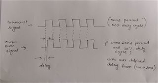
                   For your better understand I am attaching both project .zip and my configuration aim in .png file

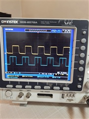
                  Also I am adding video of my outputs.

    pwm_library_timer_delay.zip

    The yellow signal is the interrupt signal and the blue signal is my pwm signal .

    Thanks & regards,
    Ram

Reply
  • Hello Karl,

                   Thank you for your valuable inputs .

                   I tried with your code and timer is triggering but instead of 1ms delay its coming increments                         automatically.

                   For your better understand I am attaching both project .zip and my configuration aim in .png file

                  Also I am adding video of my outputs.

    pwm_library_timer_delay.zip

    The yellow signal is the interrupt signal and the blue signal is my pwm signal .

    Thanks & regards,
    Ram

Children
  • Hello again, Ram

    RAM_MS said:
    Thank you for your valuable inputs .

    No problem at all, I am happy to help you.

    RAM_MS said:
    I tried with your code and timer is triggering but instead of 1ms delay its coming increments                         automatically.

    I am not sure that I understand what you mean by this - are you not seeing the button trigger a configurable timer, which calls pwm_update on expiration?
    Keep in mind that the pwm_update function is not populated in my example, so you will have to have it do something worthwhile in the pwm_update example before the example outputs anything useful when the delay expires.

    RAM_MS said:

     For your better understand I am attaching both project .zip and my configuration aim in .png file

                  Also I am adding video of my outputs.

    Oh, I see - I was under the impression that you wanted to update a PWM's duty cycle after a given delay. I was not aware that you wanted to output the same waveform out that you have received in, with an added delay.

    The simplest implementation of this would perhaps be to just have the GPIOTE IN event trigger a timer with the provided delay, that in turn sets the output pin high or low?
    You could use the PPI peripheral to have the GPIOTE in event start the TIMER, and the TIMER CC event toggle the output GPIO directly, so that none of it requires CPU intervention.

    Best regards,
    Karl

  • Hello Karl,

    The simplest implementation of this would perhaps be to just have the GPIOTE IN event trigger a timer with the provided delay, that in turn sets the output pin high or low?
    You could use the PPI peripheral to have the GPIOTE in event start the TIMER, and the TIMER CC event toggle the output GPIO directly,

    I am not getting you here .

    Can you please elaborate little more or give me a small demo of it what you are explaining.

    Thanks & regards,
    Ram

  • Hello Ram,

    RAM_MS said:
    I am not getting you here .

    I do not understand what you mean by this, could you clarify?

    RAM_MS said:
    Can you please elaborate little more or give me a small demo of it what you are explaining.

    I do not have a demo for this, but to elaborate you could start by taking a look at how the SAADC example connects a TIMER event to a SAADC task.
    You could use the exact same approach to connect a GPIOTE EVENTS_IN event to a TIMER START task through PPI. This will make the GPIOTE event (such as a LOW to HIGH event) start the delay TIMER.
    Then, you can use the PPI peripheral in the same manner to also have the TIMER CC EVENT (timer expired) trigger a GPIOTE SET task - setting the GPIO high when the delay has passed.

    There might be other good ways of doing this as well, depending on the assumptions one could make about your application. For example, will the duty cycle of the incoming PWM always be the same, or will this change as well? Is your end goal to output the exact same waveform out, as it was received in, with only the delay added, or will you do make any sort of changes to the incoming waveform?

    Best regards,
    Karl

  • Hello Karl,

    I do not have a demo for this, but to elaborate you could start by taking a look at how the SAADC example connects a TIMER event to a SAADC task.
    You could use the exact same approach to connect a GPIOTE EVENTS_IN event to a TIMER START task through PPI. This will make the GPIOTE event (such as a LOW to HIGH event) start the delay TIMER.

    I will definitely do this a try.

    There might be other good ways of doing this as well, depending on the assumptions one could make about your application. For example, will the duty cycle of the incoming PWM always be the same, or will this change as well? Is your end goal to output the exact same waveform out, as it was received in, with only the delay added, or will you do make any sort of changes to the incoming waveform?

    Definitely ,Because I did it STM32 by using TIMER in one pulse mode and its working properly .

    As BLE is needed in this application ,I am trying to do in Nordic.

    And yes duty cycle of incoming PWM always will be same .

    Yes ,My goal is to output the same waveform out ,as it was received in, with only the delay added from (100 µs to 10ms).

    Here I am attaching the pictures of what I achieved in STM32 for your reference.

    Thanks & regards,
    Ram

  • RAM_MS said:

    Definitely ,Because I did it STM32 by using TIMER in one pulse mode and its working properly .

    As BLE is needed in this application ,I am trying to do in Nordic.

    And yes duty cycle of incoming PWM always will be same .

    Yes ,My goal is to output the same waveform out ,as it was received in, with only the delay added from (100 µs to 10ms).

    Here I am attaching the pictures of what I achieved in STM32 for your reference.

    Thank you for elaborating on the requirements and operation.
    If the duty cycle will always be the same, that makes things easier.

    Then, you might be able to do this more easily, using less resources, if you instead set up the waveform using the PWM driver to ready the waveform - setting the NRFX_PWM_FLAG_LOOP flag as the last argument of the _playback() function call - , and then have the TIMER CC event trigger the TASKS_SEQSTART[0] to start the PWM peripheral instead. Once started you could disable the GPIOTE low_to_high detection, and the PPI channels.
    This way, you will not have to continuously monitor and set/clear the output pin.
    This will ensure that the PWM sequence is started after a given delay, and run until stopped. If you need to change the delay you will need to stop the PWM, re-enable the GPIOTE in event, and re-enable the PPI channels.

    RAM_MS said:
    I will definitely do this a try.

    Great, let me know if you encounter any issues or questions!

    Best regards,
    Karl

Related