This post is older than 2 years and might not be relevant anymore
More Info: Consider searching for newer posts

How to start pwm sequence after particular time delay of gpio event?

I am working on an application where I need to start pwm sequence after particular delay (accurate delay of multiple of 100us).

I am quite new to nordic environment.

Here is my code . Can please guide me what is wrong here??

#define    Period    20000 //20ms

const nrf_drv_timer_t TIMER_LED = NRF_DRV_TIMER_INSTANCE(0);

APP_PWM_INSTANCE(PWM1,1); 

static int gpio_flag =0;

void pwm_update(void)
{
      uint32_t value;
      value = duty_1;
      ready_flag = false;
      /* Set the duty cycle - keep trying until PWM is ready... */


      while ((app_pwm_channel_duty_set(&PWM1, 0, value))&(app_pwm_channel_duty_set(&PWM1, 1, value)) == NRF_ERROR_BUSY);
 
      /* ... or wait for callback. */
      while (!ready_flag);
      APP_ERROR_CHECK(app_pwm_channel_duty_set(&PWM1, 1, value));
      APP_ERROR_CHECK(app_pwm_channel_duty_set(&PWM1, 0, value));

}


void in_pin_handler(nrf_drv_gpiote_pin_t pin, nrf_gpiote_polarity_t action)
{
   gpio_flag =1;
   nrf_drv_timer_enable(&TIMER_LED);

   
}

void timer0_handler(nrf_timer_event_t event_type, void* p_context)
{
  switch (event_type)
    {
        case NRF_TIMER_EVENT_COMPARE0:
             timer_flg =1;
             nrf_drv_timer_clear(&TIMER_LED);
             gpio_flag=0;
             pwm_update();
            break;

        default:
            //Do nothing.
            break;
    }
}


void timer_init(void)
{
    uint32_t time_us = 500; 
    uint32_t time_ticks;
    uint32_t err_code = NRF_SUCCESS;

    nrf_drv_timer_config_t timer_cfg = NRF_DRV_TIMER_DEFAULT_CONFIG;
    err_code = nrf_drv_timer_init(&TIMER_LED, &timer_cfg, timer0_handler);
    APP_ERROR_CHECK(err_code);

    time_ticks = nrf_drv_timer_us_to_ticks(&TIMER_LED, time_us);
    nrf_drv_timer_compare(
         &TIMER_LED, NRF_TIMER_CC_CHANNEL0, time_ticks, true);

    
}

Parents
  • Hello,

    I am quite new to nordic environment.

    Welcome! Please do not hesitate to ask if you should have any questions.

    I am working on an application where I need to start pwm sequence after particular delay (accurate delay of multiple of 100us).

    Could you show me the entirety of your main.c code?
    Right now I do not see where you setup your gpio for triggering the enabling of the timer, so I am not sure that the timer is ever started, for instance.

    Could you also elaborate on what behavior you are seeing, and how this differs from what you would expect? Does the device reset for example, or is it just that 'nothing' is happening, for example?

    Best regards,
    Karl

  • Hello Karl,

    Right now I do not see where you setup your gpio for triggering the enabling of the timer, so I am not sure that the timer is ever started, for instance.

    void in_pin_handler(nrf_drv_gpiote_pin_t pin, nrf_gpiote_polarity_t action)
    {
       gpio_flag =1;
       nrf_drv_timer_enable(&TIMER_LED);
    
       
    }

    Could you also elaborate on what behavior you are seeing, and how this differs from what you would expect? Does the device reset for example, or is it just that 'nothing' is happening, for example?

    I am not getting the delay I am expecting.

    I think I have done some wrong configuration in linking to timer from gpio interrupt routine. 

    Best regards,
    Ram


  • Hello Karl,

    This looks mostly correct, but I cant see that you have connected the GPIOTE IN EVENT to the TIMER's START task through PPI anywher

    static void ppi_init(void)
    {
        uint32_t err_code = NRF_SUCCESS;
    
        err_code = nrf_drv_ppi_init();
        APP_ERROR_CHECK(err_code);
    
        // Allocate the channel from the available PPI channels
        err_code = nrf_drv_ppi_channel_alloc(&ppi_channel_1);
        APP_ERROR_CHECK(err_code);
    
        err_code = nrf_drv_ppi_channel_assign(ppi_channel_1,
                                              nrf_drv_gpiote_in_event_addr_get(PIN_IN),
                                              nrf_drv_timer_task_address_get(&PWM_DELAY_TIMER,
                                                                             NRF_TIMER_TASK_START));
        APP_ERROR_CHECK(err_code);
    
    
        err_code = nrf_drv_ppi_channel_alloc(&ppi_channel_2);
        APP_ERROR_CHECK(err_code);
    
        compare_event_addr = nrf_drv_timer_task_address_get(&PWM_DELAY_TIMER,NRF_TIMER_CC_CHANNEL0);
        pwm_task_addr =  nrf_drv_pwm_task_address_get(&m_pwm0,NRF_PWM_TASK_SEQSTART0);
    
        err_code = nrf_drv_ppi_channel_assign(ppi_channel_2, compare_event_addr,pwm_task_addr);
        APP_ERROR_CHECK(err_code);
    
    
        err_code = nrf_drv_ppi_channel_enable(ppi_channel_1);
        APP_ERROR_CHECK(err_code);
    
        err_code = nrf_drv_ppi_channel_enable(ppi_channel_2);
        APP_ERROR_CHECK(err_code);
     }
    
    static void gpio_init(void)
    {
        ret_code_t err_code;
        
    
        err_code = nrf_drv_gpiote_init();
        APP_ERROR_CHECK(err_code);
    
        
        nrf_drv_gpiote_in_config_t in_config = GPIOTE_CONFIG_IN_SENSE_LOTOHI(true);
        in_config.pull = NRF_GPIO_PIN_PULLDOWN;
    
        err_code = nrf_drv_gpiote_in_init(PIN_IN, &in_config, in_pin_handler);
        APP_ERROR_CHECK(err_code);
    
        nrf_drv_gpiote_in_event_enable(PIN_IN, true);
    }
    
    void timers_init(void)
    {
        uint32_t err_code;
        uint32_t timer_ticks;
        
        nrfx_timer_config_t timer_cfg = NRFX_TIMER_DEFAULT_CONFIG;
        timer_cfg.frequency = NRF_TIMER_FREQ_1MHz;
        err_code = nrfx_timer_init(&PWM_DELAY_TIMER, &timer_cfg,pwm_delay_timeout_handler);
        APP_ERROR_CHECK(err_code);
    
        timer_ticks = nrfx_timer_us_to_ticks(&PWM_DELAY_TIMER, PWM_DELAY_US);
    
        nrfx_timer_extended_compare(&PWM_DELAY_TIMER, 
                                      NRF_TIMER_CC_CHANNEL0, 
                                      timer_ticks,
                                      NRF_TIMER_SHORT_COMPARE0_CLEAR_MASK,
                                      true);
    
       nrfx_timer_enable(&PWM_DELAY_TIMER);
    
    }
    
    
    static void pwm_init(void)
    {
        nrf_drv_pwm_config_t const config0 =
        {
            .output_pins =
            {
                OUTPUT_PIN, // channel 0
                OUTPUT_PIN2,             // channel 1
                NRF_DRV_PWM_PIN_NOT_USED,             // channel 2
                NRF_DRV_PWM_PIN_NOT_USED,             // channel 3
            },
            .irq_priority = APP_IRQ_PRIORITY_LOWEST,
            .base_clock   = NRF_PWM_CLK_1MHz,
            .count_mode   = NRF_PWM_MODE_UP,
            .top_value    = 20000,
            .load_mode    = NRF_PWM_LOAD_INDIVIDUAL,
            .step_mode    = NRF_PWM_STEP_AUTO
        };
        // Init PWM without error handler
        APP_ERROR_CHECK(nrf_drv_pwm_init(&m_pwm0, &config0, NULL));
    
        seq_values->channel_0 = duty ;
        seq_values->channel_1 = duty | 0x8000;
        
        APP_ERROR_CHECK(nrf_drv_pwm_simple_playback(&m_pwm0, &seq, 1,NRF_DRV_PWM_FLAG_LOOP|NRF_DRV_PWM_FLAG_START_VIA_TASK));
                    
    }
    

    So this scenario needed two ppi connection .

    1-> From GPIOTE  IN   EVENT to the TIMER START 

    2->TIMER COMPATRE to PWM_TASK_SEQSTART .

    I am implemented in this way ,Please verify is this connection is right now??


  • RAM_MS said:

    So this scenario needed two ppi connection .

    1-> From GPIOTE  IN   EVENT to the TIMER START 

    2->TIMER COMPATRE to PWM_TASK_SEQSTART .

    Yes, your scenario requires two PPI connections.

    RAM_MS said:
    I am implemented in this way ,Please verify is this connection is right now??

    Yes, I do not immediately spot anything wrong with this configuration.
    What do you see when you now attempt to compile and run this program?

    Best regards,
    Karl

  • Hello Karl,

    What do you see when you now attempt to compile and run this program?

    compiled successfully with zero error but pwm output isn't coming , that means its not triggering.

    But below error coming.

    <error> app: Fatal error

    <warning> app: System reset

    Best regards,
     Ram

  • Please make sure to have DEBUG defined in your preprocessor defines, like shown in the included image:

    This will make the logger output a detailed error message whenever a non-NRF_SUCCESS error is passed to an APP_ERROR_CHECK.
    Try this, and let me know what the logger says when this happens.

    Best regards,
    Karl

  • Hello Karl,

    Try this, and let me know what the logger says when this happens.

    <info> app: PPI example started.

    <info> app: LED started.

    <info> app: gpio started.

    <info> app: timer started.

    <error> app: ERROR 1073856524 [Unknown error code] at C:\Nordic\DeviceDownload\nRF5SDK1702d674dde\nRF5_SDK_17.0.2_d674dde\examples\my proj\pwm_common_mode\main.c:176

    PC at: 0x00006BA5

    <error> app: End of error report

    And my main code is:

    int main(void)
    {
    
        uint32_t err_code;
    
        err_code = NRF_LOG_INIT(NULL);
        APP_ERROR_CHECK(err_code);
    
        NRF_LOG_DEFAULT_BACKENDS_INIT();
        ppi_init();
        NRF_LOG_INFO("PPI example started.");
        bsp_board_init(BSP_INIT_LEDS);
        NRF_LOG_INFO("LED started.");
        gpio_init();
        NRF_LOG_INFO("gpio started.");
        timers_init();
        NRF_LOG_INFO("timer  started.");
        pwm_init();
        
        NRF_LOG_INFO("pwm started.");
         
        unsigned int val;
        
        while (1)
        {


        }
    }

    This means Its coming from pwm_init() function.

    Best regards,
     Ram

Reply
  • Hello Karl,

    Try this, and let me know what the logger says when this happens.

    <info> app: PPI example started.

    <info> app: LED started.

    <info> app: gpio started.

    <info> app: timer started.

    <error> app: ERROR 1073856524 [Unknown error code] at C:\Nordic\DeviceDownload\nRF5SDK1702d674dde\nRF5_SDK_17.0.2_d674dde\examples\my proj\pwm_common_mode\main.c:176

    PC at: 0x00006BA5

    <error> app: End of error report

    And my main code is:

    int main(void)
    {
    
        uint32_t err_code;
    
        err_code = NRF_LOG_INIT(NULL);
        APP_ERROR_CHECK(err_code);
    
        NRF_LOG_DEFAULT_BACKENDS_INIT();
        ppi_init();
        NRF_LOG_INFO("PPI example started.");
        bsp_board_init(BSP_INIT_LEDS);
        NRF_LOG_INFO("LED started.");
        gpio_init();
        NRF_LOG_INFO("gpio started.");
        timers_init();
        NRF_LOG_INFO("timer  started.");
        pwm_init();
        
        NRF_LOG_INFO("pwm started.");
         
        unsigned int val;
        
        while (1)
        {


        }
    }

    This means Its coming from pwm_init() function.

    Best regards,
     Ram

Children
  • Hello again, Ram

    RAM_MS said:

    <error> app: ERROR 1073856524 [Unknown error code] at C:\Nordic\DeviceDownload\nRF5SDK1702d674dde\nRF5_SDK_17.0.2_d674dde\examples\my proj\pwm_common_mode\main.c:176

    PC at: 0x00006BA5

    Exactly which function call returned the error code passed to an APP_ERROR_CHECK on line 176 of main?
    Could you share the entire pwm_init function as it currently is? To proceed we will need to pinpoint which APP_ERROR_CHECK that triggered the reset, and which function generated the error.

    Best regards,
    Karl

  • Hello Karl,

    Exactly which function call returned the error code passed to an APP_ERROR_CHECK on line 176 of main?
    Could you share the entire pwm_init function as it currently is? To proceed we will need to pinpoint which APP_ERROR_CHECK that triggered the reset, and which function generated the error.

    Here is my entire  pwm_init function as it currently is.

    And on line 176  [[APP_ERROR_CHECK(nrf_drv_pwm_simple_playback(&m_pwm0, &seq, 1,NRF_DRV_PWM_FLAG_LOOP | NRF_DRV_PWM_FLAG_START_VIA_TASK));]]

    static void pwm_init(void)
    {
        nrf_drv_pwm_config_t const config0 =
        {
            .output_pins =
            {
                OUTPUT_PIN, // channel 0
                OUTPUT_PIN2,             // channel 1
                NRF_DRV_PWM_PIN_NOT_USED,             // channel 2
                NRF_DRV_PWM_PIN_NOT_USED,             // channel 3
            },
            .irq_priority = APP_IRQ_PRIORITY_LOWEST,
            .base_clock   = NRF_PWM_CLK_1MHz,
            .count_mode   = NRF_PWM_MODE_UP,
            .top_value    = 20000,
            .load_mode    = NRF_PWM_LOAD_INDIVIDUAL,
            .step_mode    = NRF_PWM_STEP_AUTO
        };
        // Init PWM without error handler
        APP_ERROR_CHECK(nrf_drv_pwm_init(&m_pwm0, &config0, NULL));
    
        seq_values->channel_0 = duty ;
        seq_values->channel_1 = duty | 0x8000;
        
        APP_ERROR_CHECK(nrf_drv_pwm_simple_playback(&m_pwm0, &seq, 1,NRF_DRV_PWM_FLAG_STOP | NRF_DRV_PWM_FLAG_START_VIA_TASK));
                    
    }

    Best regards,
     Ram

  • Oh, I see now - you should not do an APP_ERROR_CHECK on the return value from nrf_drv_pwm_simple_playback, as mention in its API Reference it returns the address of the task you should trigger to start the sequence (this address should be equal to the one you got from the addres_get function in the PPI setup).
    The documentation exempt reads:

    Address of the task to be triggered to start the playback if the NRFX_PWM_FLAG_START_VIA_TASK flag was used, 0 otherwise.

    Best regards,
    Karl

  • Hello Karl,

    Oh, I see now - you should not do an APP_ERROR_CHECK on the return value from nrf_drv_pwm_simple_playback, as mention in its API Reference it returns the address of the task you should trigger to start the sequence (this address should be equal to the one you got from the addres_get function in the PPI setup).

    You mean to say that what Get from  pwm_task_addr= nrf_drv_pwm_task_address_get(&m_pwm0,NRF_PWM_TASK_SEQSTART0);

    Same should use here  like pwm_task_addr=nrf_drv_pwm_simple_playback(&m_pwm0, &seq, 1,NRF_DRV_PWM_FLAG_STOP | NRF_DRV_PWM_FLAG_START_VIA_TASK);


    {
    //ppi init part
    compare_event_addr = nrf_drv_timer_task_address_get(&PWM_DELAY_TIMER,NRF_TIMER_CC_CHANNEL0);
    pwm_task_addr =  nrf_drv_pwm_task_address_get(&m_pwm0,NRF_PWM_TASK_SEQSTART0);
    
    err_code = nrf_drv_ppi_channel_assign(ppi_channel_2, compare_event_addr,pwm_task_addr);
    }
    
    {
    // pwm init part 
    pwm_task_addr=nrf_drv_pwm_simple_playback(&m_pwm0, &seq, 1,NRF_DRV_PWM_FLAG_LOOP | NRF_DRV_PWM_FLAG_START_VIA_TASK);
    }

    Thanks Karl It is working now .

    Many Many Thanks .

    But now there is a problem.

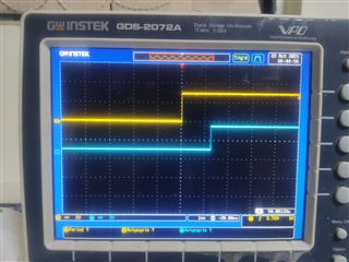
    1)the timing is not correct .Here I am attaching the snapshot of it 

    From the picture you can clearly see that the delay time is more than 1ms .

    How can I make it exact??

    Best regards,
     Ram

  • Hello again, Ram

    RAM_MS said:

    You mean to say that what Get from  pwm_task_addr= nrf_drv_pwm_task_address_get(&m_pwm0,NRF_PWM_TASK_SEQSTART0);

    Same should use here  like pwm_task_addr=nrf_drv_pwm_simple_playback(&m_pwm0, &seq, 1,NRF_DRV_PWM_FLAG_STOP | NRF_DRV_PWM_FLAG_START_VIA_TASK);

    Yes, you could use the address returned by nrf_drv_pwm_simple_playback as the input to the PPI connection.

    RAM_MS said:

    Thanks Karl It is working now .

    Many Many Thanks .

    But now there is a problem.

    Great, I am happy to hear that we have progressed closer to the desired functionality.

    RAM_MS said:

    From the picture you can clearly see that the delay time is more than 1ms .

    How can I make it exact??

    This does indeed not look correct - that is quite the added delay, more than 200 µs it seems.
    Could you clarify exactly what you are scoping here with the blue and yellow line? I assume it is the inputted PWM and the resulting delayed PWM output, but it would be good if you could confirm / specify this.

    To debug this we will need to find out where in the chain of events this delay is introduced.
    Could you try this again with different delays, so we may see if there is an issue with the timer configuration for instance?
    Alternatively, as a debugging measure, you could change to have the TIMER CC event connected to a pin toggle TASK, so we may verify that the timer is producing the correct delay.
    I look forward to hearing what you observe when you test this!

    Best regards,
    Karl

Related