This post is older than 2 years and might not be relevant anymore
More Info: Consider searching for newer posts

Uart baudrate is inaccurate

Hello

The Uart Baudrate is initiliazed at 115200 baud but i the  BLE nRF52833 is sending with  about 115900.

I try to switch to hf clock but the baudrate is to high.

    // Request and wait for it to be ready.
    err_code = sd_clock_hfclk_request();
    APP_ERROR_CHECK(err_code);

    uint32_t hfclk_is_running = 0;

    while (!hfclk_is_running)
    {
        APP_ERROR_CHECK(sd_clock_hfclk_is_running(&hfclk_is_running) );
    }    

  • Hi,

    Sorry for the late reply. How are you measuring the uart baudrate? Is this happening on a nRF52833 DK or a custom board? Have you check the accuracy of the external crystal and tuned the crystal capacitors?

    Is the baudrate still too high if you are using the internal oscillator? It may be that the external crystal capacitors are not tuned correctly so it's oscillating too fast.

    Baudrate accuracy depends both on accuracy of the clock source (HFXO or HFINT) and division error in the baudrate generator. Actual baudrates when accounting for division errors are listed here: https://infocenter.nordicsemi.com/index.jsp?topic=%2Fps_nrf52833%2Fuarte.html&anchor=register.BAUDRATE

    Best regards,

    Marjeris

  • yes, we checked the external crystal and the cyrstal is accurate.

    this is defined in sdk_config.h

    // <e> NRFX_CLOCK_ENABLED - nrfx_clock - CLOCK peripheral driver
    //==========================================================
    #ifndef NRFX_CLOCK_ENABLED
    #define NRFX_CLOCK_ENABLED 1
    #endif
    // <o> NRFX_CLOCK_CONFIG_LF_SRC  - LF Clock Source
     
    // <0=> RC
    // <1=> XTAL
    // <2=> Synth
    // <131073=> External Low Swing
    // <196609=> External Full Swing

    #ifndef NRFX_CLOCK_CONFIG_LF_SRC
    #define NRFX_CLOCK_CONFIG_LF_SRC 1
    #endif

    after swithed on the hf clock (see above ) both are running

          if( nrf_drv_clock_hfclk_is_running() )
          {
            // Start execution.

           // nrf_drv_clock_hfclk_release();                                 ->this raises an error if implented

            NRF_LOG_INFO("HFCLK running");
          }
          if( nrf_drv_clock_lfclk_is_running() )
          {
            NRF_LOG_INFO("LFCLK running");
          }

    how can I stop the LFCLK and start/release the HFCLK.

  • Hi,

    RSchmale said:
    yes, we checked the external crystal and the cyrstal is accurate.

    Do you have a scope capture? Did you check that the requirements for crystal accuracy was inside of the recommended <40 ppm margin?

    RSchmale said:

    how can I stop the LFCLK and start/release the HFCLK.

    You should call nrf_drv_clock_hfclk_request() to request the clock to start. If the clock is not running nrf_drv_clock_hfclk_is_running should return 'false' when called.

    RSchmale said:
      // nrf_drv_clock_hfclk_release();                                 ->this raises an error if implented

    This call will stop the clock if it's running. If you are getting an error from it it could be that the clock is not started.

    Best regards,

    Marjeris

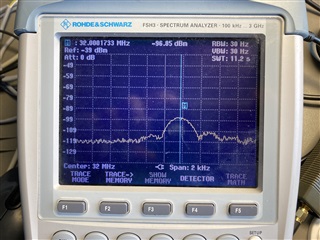
  • Quartz und 5,5ppmHello Marjeris

    As you can see the ppm margin is at 5.5ppm

  • Hi Ralf,

    You are working on a custom board right? And are you seing this error on all boards or just one?

    In my previous answer I ment the carrier frequency accuracy. We measure the crystal accuracy by setting up a single TX carrier on the radio to then verify if the TX carrier is outside the accepted range. This is explained in the RF performance test and guidelines whitepaper. If working on a custom board you need to check the frequency accuracy and tune the crystal capacitors values accordingly.

    If the TX carrier frequency is outside of the accepted window there are two issues you should check:

    • Crystal accuracy specification.
    • Crystal load.

    So check the datasheet of the crystal you are using, check that it complies with the crystal specifications available in the nRF52833 product specification. Then check the crystals' load capacitance (CL) in the crystal datasheet. The load capacitance should be choose accordingly to this value and the formula:

    C1 = C2 = 2CL - C_pcb - C_pin

    Cl: Load capacitance of the crystal (found in the crystal datasheet)

    C_pcb + C_pin is approximately 4 pF.


    But these values should be adjusted depending on what you see on the scope when measuring the frequency accuracy.

    Let me know if my assumptions are perhaps incorrect. If you are for example testing on a nRF52833 DK the problem will not be on the hardware but probably on the software side...

    Best regards,

    Marjeris

Related