GPIO, interrupt & timer latencies larger than expected.

I'm trying to implement communication protocol that involves clock and bidirectional I/O line. Clock signal is coming from an external device and expected to be in 1-5MHz range. I/O pin state is read or changed every N clock pulses.

So I expected to use Timer/Counter peripherial which uses external clock as a source, i.e. each external clock pulse increments the counter and on compare event it is reset to zero and some other actions are done, like sensing I/O input or sending something back on the same I/O pin.

minimal example:


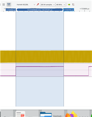
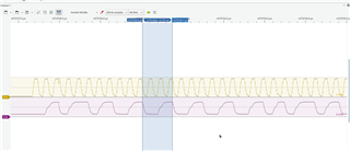
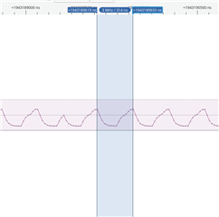
After long investigations using oscilloscope, I've found out that timer skips many clock pulses and compare events are triggered less frequently than expected.

void timer1_init(void)
{ 
 nrf_drv_timer_config_t timer_cfg = NRF_DRV_TIMER_DEFAULT_CONFIG;
 timer_cfg.mode = NRF_TIMER_MODE_COUNTER;
 timer_cfg.bit_width = NRF_TIMER_BIT_WIDTH_16;
 nrf_drv_timer_init(&clock_counter, &timer_cfg, empty_timer_handler);

 nrfx_timer_compare(&clock_counter, NRF_TIMER_CC_CHANNEL0, N, true);

}
void ppi_init(void)
{  
 nrf_drv_ppi_channel_alloc(&ppi_channel1);
 nrf_drv_ppi_channel_alloc(&ppi_channel2);
 
 nrfx_gpiote_in_config_t clock_pin_conf = NRFX_GPIOTE_CONFIG_IN_SENSE_LOTOHI(true);
 nrfx_gpiote_in_init(CLOCK_PIN, &clock_pin_conf, empty_gpiote_handler);
  
 nrf_drv_ppi_channel_assign(ppi_channel1,
                            nrfx_gpiote_in_event_addr_get(CLOCK_PIN),
                            nrf_drv_timer_task_address_get(&clock_counter,
                                                           NRF_TIMER_TASK_COUNT));


 //reset counter on COMPARE0 event
 nrf_drv_ppi_channel_assign(ppi_channel2,
                            nrf_drv_timer_event_address_get(&clock_counter,
                                                            NRF_TIMER_EVENT_COMPARE0),
                            nrf_drv_timer_task_address_get(&clock_counter,
                                                           NRF_TIMER_TASK_CLEAR));
  
 nrf_drv_ppi_channel_enable(ppi_channel1);
 nrf_drv_ppi_channel_enable(ppi_channel2);

 nrfx_gpiote_in_event_enable(CLOCK_PIN, true);
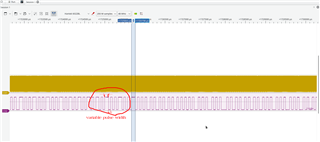
}
I've tried to toggle test GPIO pin state in GPIOTE event handler callback for debugging, and it appears it is triggered on every 5-10 input pulses instead of every rising edge as expected. It could mean GPIO events or interrupts have unexpectedly big latency.

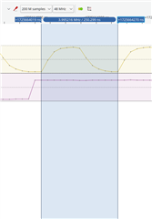
I tried to avoid using any additional peripherials and poll the clock pin in a loop, and the best result I was able to achieve is that output debug pin is toggled on every 3 incoming pulses. That means NRF52 takes too long to read changed GPIO pin state, unexpectedly long for CPU running at 64MHz and peripherial clocks at 16 or 32 MHz

 int clockstate = 0;


 NRF_POWER->TASKS_CONSTLAT = 1;

 nrfx_clock_init(empty_clock_event_handler);
 nrfx_clock_hfclk_start();
 while(!nrfx_clock_hfclk_is_running());


nrf_gpio_cfg_output(19);
 __disable_irq();

  while(1)
 {
    int newclockstate;
    newclockstate = nrf_gpio_pin_read(CLOCK_PIN);

    if (clockstate != newclockstate)
    {
      nrf_gpio_pin_write(19, newclockstate);
      clockstate = newclockstate;
    }
 }

Channel1 -- input clock, Channel2 -- output debug pin

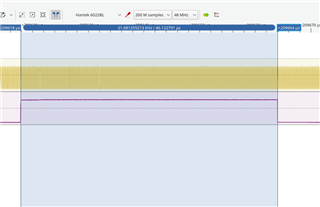
Even just changing the state of output debug pin results in only ~3.1MHz output

 int clockstate = 0;


  NRF_POWER->TASKS_CONSTLAT = 1;

  nrfx_clock_init(empty_clock_event_handler);
  nrfx_clock_hfclk_start();
  while(!nrfx_clock_hfclk_is_running());

  nrf_gpio_cfg_output(19);
  __disable_irq();
  while(1)
  {
    nrf_gpio_pin_write(19, (clockstate++) & 0x1);
  }

output signal

Is NRF52832 (or all NRF52) that bad and slow in peripherials, or am I doing something wrong?
Why there is no information about GPIO switching times in datasheet?

Is it possible to achieve my task to sense 5MHz clock using NRF52832 or NRF52810 at all?
I thought about using SPIS (SPI slave peripherial) as a possible workaround,

datasheet says it can handle up to 8Mbit input clock,

and probably MOSI/MISO pin roles can be changed on the fly and assigned to the same I/O pin for input and output,

as I need to change I/O pin state on every 200-300 clock, not on every clock pulse, so TX register can be fed with

all zeroes/all ones value.

Parents Reply Children
  • Tried to apply,

    there is some effect,

    but timer compare events are still triggered at variable time periods

  • What about possibility of using SPIS peripherial for counting incoming clock pulses?

  • basically I think about connecting clock line to SPIS CLK, leave MOSI, MISO unconnected, make some loop connection from one GPIO to chip select pin in order to emulate started transaction. And then count number of bytes received. Something like this.

  • Hi,


    somename said:
    basically I think about connecting clock line to SPIS CLK, leave MOSI, MISO unconnected, make some loop connection from one GPIO to chip select pin in order to emulate started transaction. And then count number of bytes received. Something like this.

    If you always receive byte-aligned amount of pulses, that will work.


    In your current design, could you try to:

    * Omit the GPIOTE event handler

    * Use TIMER SHORTS to clear the timer on COMPARE0 instead of a PPI channel

    * Lower the input frequency (let's say 2 MHz) to see how it behaves then?


    Kind regards,

    Håkon

  • 1. Do you mean to have an empty event handler and pass false to disable interrupts in

    nrfx_gpiote_in_event_enable(INPUT_CLOCK_PIN, false);

    ? Or there other ways to omit the handler too?

    2. Ok, tried this.

    3. I can't control input frequency for this task, it is decied by other device. In this specific case it is 4MHz according to oscilloscope measurements.

    Here is the complete minimal compilable example that demonstrates the problem.
    There is an input 4MHz clock on clock pin 3, and output test signal is generated on pin 19. Both are recorded by oscilloscope.  Output pin is toggled in timer compare event.

    Is everything in this code ok?

    #include "nrfx_ppi.h"
    #include "nrfx_timer.h"
    #include "nrfx_gpiote.h"
    #include "nrf_delay.h"
    #include "nrf_gpio.h"
    #include "nrf_clock.h"
    #include "nrfx_clock.h"
    
    
    #define INPUT_CLOCK_PIN 3
    #define OUTPUT_TEST_SIGNAL_PIN 19
    #define TIMER_COMPARE_VALUE 372
    
    static nrf_ppi_channel_t ppi_channel1;
    const nrfx_timer_t clock_counter = NRFX_TIMER_INSTANCE(1);
    
    static void  empty_gpiote_handler(nrfx_gpiote_pin_t pin, nrf_gpiote_polarity_t action)
    {
    }
    
    void empty_clock_event_handler(nrfx_clock_evt_type_t event)
    {
    }
    
    static void timer_handler(nrf_timer_event_t event_type, void * p_context)
    {
      if (event_type != NRF_TIMER_EVENT_COMPARE0)
        return;
      // toggle output pin on each timer compare event
      if (nrf_gpio_pin_out_read(OUTPUT_TEST_SIGNAL_PIN))
        NRF_P0->OUTCLR = 1 << OUTPUT_TEST_SIGNAL_PIN;
      else
        NRF_P0->OUTSET = 1 << OUTPUT_TEST_SIGNAL_PIN;
    }
    
    int main(void)
    {
      NRF_POWER->TASKS_CONSTLAT = 1;
    
      nrfx_clock_init(empty_clock_event_handler);
      nrfx_clock_hfclk_start();
      while(!nrfx_clock_hfclk_is_running());
    
      nrf_gpio_cfg(INPUT_CLOCK_PIN,
                   NRF_GPIO_PIN_DIR_INPUT,
                   NRF_GPIO_PIN_INPUT_CONNECT,
                   NRF_GPIO_PIN_NOPULL,
                   NRF_GPIO_PIN_S0S1,
                   NRF_GPIO_PIN_NOSENSE);
    
      nrf_gpio_cfg(OUTPUT_TEST_SIGNAL_PIN,
                   NRF_GPIO_PIN_DIR_OUTPUT,
                   NRF_GPIO_PIN_INPUT_DISCONNECT,
                   NRF_GPIO_PIN_NOPULL,
                   NRF_GPIO_PIN_H0H1,
                   NRF_GPIO_PIN_NOSENSE);
    
      nrfx_gpiote_init();
    
      nrfx_ppi_channel_alloc(&ppi_channel1);
    
      nrfx_gpiote_in_config_t clock_pin_conf = NRFX_GPIOTE_CONFIG_IN_SENSE_LOTOHI(true);
      nrfx_gpiote_in_init(INPUT_CLOCK_PIN, &clock_pin_conf, empty_gpiote_handler);
    
      *(volatile uint32_t *)(NRF_GPIOTE_BASE + 0x600 + (4 * 0)) = 1;//errata [155] GPIOTE: IN event may occur more than once on input edge
    
      nrfx_ppi_channel_assign(ppi_channel1,
                                 nrfx_gpiote_in_event_addr_get(INPUT_CLOCK_PIN),
                                 nrfx_timer_task_address_get(&clock_counter,
                                                                NRF_TIMER_TASK_COUNT));
      nrfx_ppi_channel_enable(ppi_channel1);
    
      nrfx_gpiote_in_event_enable(INPUT_CLOCK_PIN, false);
    
      nrfx_timer_config_t timer_cfg = NRFX_TIMER_DEFAULT_CONFIG;
      timer_cfg.mode = NRF_TIMER_MODE_COUNTER;
      timer_cfg.bit_width = NRF_TIMER_BIT_WIDTH_16;
      nrfx_timer_init(&clock_counter, &timer_cfg, timer_handler);
    
      nrfx_timer_clear(&clock_counter);
      nrfx_timer_compare(&clock_counter, NRF_TIMER_CC_CHANNEL0, TIMER_COMPARE_VALUE, true);
    
      nrf_timer_shorts_enable(clock_counter.p_reg, NRF_TIMER_SHORT_COMPARE0_CLEAR_MASK);
      nrf_timer_event_clear(clock_counter.p_reg, NRF_TIMER_EVENT_COMPARE0);
      nrfx_timer_enable(&clock_counter);
    
      while(1)
      {
      }
    
      return 0;
    }


    Issue that I see here that output pulse period is not fixed and variates.

    If there is an input 4MHz clock, and timer compare value is set to 372,

    I expect output pulse width (time between two compare events) to be

    1/4000000*372 = 93 us, but shortest pulses visible on a picture are about 45us each,

    i.e compare event happens 2x more times than expected?

Related