
I understand I'd be using 16MHz timer for this and it worked on Arduino nano.
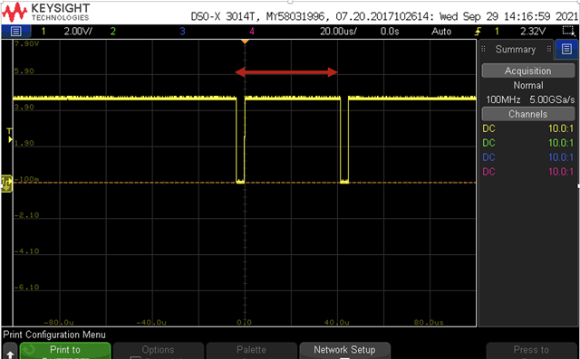
I'm trying to measure the distance above with nRF52840 dongle.
Those two edges come in every 10ms(100Hz)
The timer value would have to be captured and subtracted to between 1 and 1100 approximately.
This distance value would have to be converted in to 8bit data and when the dongle receives 10 of these, it should send them over bluetooth(BLE).
I'm struggling to get collect the data correctly. Here's my work done so far.
example of ble_app_uart i added this.
uint32_t time1=0;
uint32_t time2=0;
uint32_t distance_1=0;
uint8_t data_high=0;
uint8_t data_array[BLE_NUS_MAX_DATA_LEN];
uint8_t index1 = 0;
bool time_flag = true;
void in_pin_handler(nrf_drv_gpiote_pin_t pin, nrf_gpiote_polarity_t action)
{
    uint32_t       err_code;
    if (time_flag){
        time1 = nrfx_timer_capture(&m_timer_capture, NRF_TIMER_CC_CHANNEL0);
    }else{
        time2 = nrfx_timer_capture(&m_timer_capture, NRF_TIMER_CC_CHANNEL0);;
    }
    time_flag = !time_flag;
    NRF_LOG_INFO("time1 = %d, time2 = %d", time1, time2);

    distance_1 = app_timer_cnt_diff_compute(time2,time1);
    NRF_LOG_INFO("%d", distance_1);
    if (distance_1 < 1200){
        data_high = fmin( fmax(round((distance_1 - 16.0 - 52.0 - 16.0 + 4.0) / 4.0), 0.0), 255.0);
        data_array[index1]=data_high;
        index1++;

        if (index1 >= 10)
        {
            if (index1 >= 0)
            {
                do
                {
                    NRF_LOG_INFO("H");
                    uint16_t length = 10;
                    err_code = ble_nus_data_send(&m_nus, data_array, &length, m_conn_handle);
                    if ((err_code != NRF_ERROR_INVALID_STATE) &&
                        (err_code != NRF_ERROR_RESOURCES) &&
                        (err_code != NRF_ERROR_NOT_FOUND))
                    {
                        APP_ERROR_CHECK(err_code);
                    }
                } while (err_code == NRF_ERROR_RESOURCES);
            }
            index1 = 0;
        }
    }


}

/**
 * @brief Function for configuring: PIN_IN pin for input sensing
 */
static void gpiote_init(void)
{
    ret_code_t err_code;

    err_code = nrf_drv_gpiote_init();
    APP_ERROR_CHECK(err_code);

    nrf_drv_gpiote_in_config_t in_config = GPIOTE_CONFIG_IN_SENSE_HITOLO(true);
    in_config.pull = NRF_GPIO_PIN_PULLDOWN;

    err_code = nrf_drv_gpiote_in_init(PIN_IN, &in_config, in_pin_handler);
    APP_ERROR_CHECK(err_code);

    nrf_drv_gpiote_in_event_enable(PIN_IN, true);
}

/**@brief Function for initializing the timer module.
 */
static void timers_init(void)
{
    ret_code_t err_code = app_timer_init();
    APP_ERROR_CHECK(err_code);

    nrf_drv_timer_config_t timer_cfg = NRF_DRV_TIMER_DEFAULT_CONFIG;
    err_code = nrfx_timer_init(&m_timer_capture, &timer_cfg, NULL);
    APP_ERROR_CHECK(err_code);

    nrf_drv_timer_enable(&m_timer_capture);

}
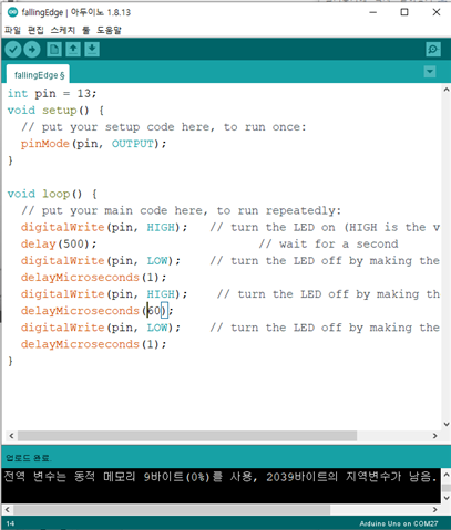
Arduino uno runs this.
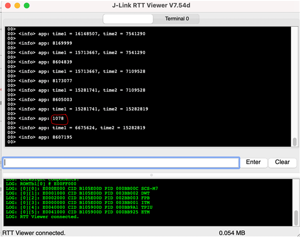
The log prints out like this as you can see in_pin_handler is not getting called fast enough and it's missing a lot of data. Too big values don't get sent.
but still once in a while the collected data reached 10 so it sends over bluetooth(BLE) and this is what I've got.
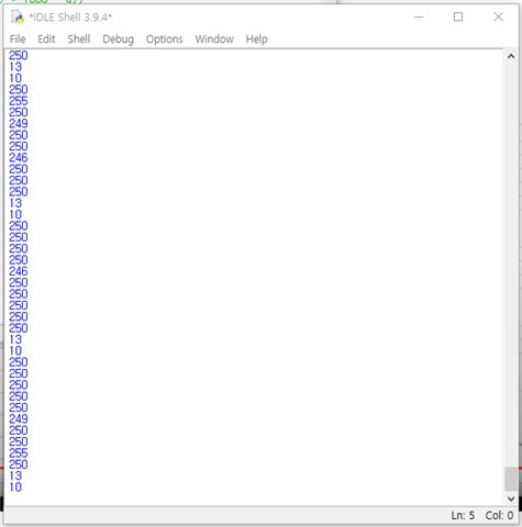
But this python data is running very slow because of all the missing data. 10data in approximately 2 minutes every time.
it seems it isn't impossible to measure such a short distance like 1078. Why is it happening so rarely?
What's the best way?

