ADC - First read is always wrong

Hi, 

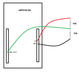
I have been playing around with the nRF9160 DK trying to get it reading a range of sensors, so far with success, however I have found an issue which has stumped me. I am using ADC0 to read a voltage. Although this is intended for a pressure transducer, for debugging I have just put the 5V out through a resistive divider (10K / 10K) and the ADC successfully reads 2.5V. 

However, when the program is first run, the very first ADC reading is around 50. The next one, and all instances after, it reads correctly (around 3500 - using 3V VDD as reference and gain of 1/4, 12-bit resolution). 

I assumed this may be due to acquisition time, but I tried a few different values and nothing helped. 

I wont post the full code, but here is the config and read code

#define ADC_RESOLUTION 12
#define ADC_GAIN ADC_GAIN_1_4
#define ADC_REFERENCE ADC_REF_VDD_1_4
#define ADC_ACQUISITION_TIME ADC_ACQ_TIME(ADC_ACQ_TIME_MICROSECONDS, 10)
#define ADC_1ST_CHANNEL_ID 0  
#define ADC_1ST_CHANNEL_INPUT NRF_SAADC_INPUT_AIN0

#define BUFFER_SIZE 1
static uint16_t m_sample_buffer[BUFFER_SIZE];

static struct adc_channel_cfg channel_cfg = {
	.gain 				= ADC_GAIN,
	.reference 			= ADC_REFERENCE,
	.acquisition_time 	= ADC_ACQUISITION_TIME,
	.differential 		= 0,
	.channel_id			= ADC_1ST_CHANNEL_INPUT ,
	.input_positive 	= SAADC_CH_PSELP_PSELP_AnalogInput0,
};

static int adc_sample(void)
{
	int ret;

		struct adc_sequence sequence = {
		.channels    = BIT(channel_cfg.channel_id),
		.buffer      = &m_sample_buffer,
		.buffer_size = sizeof(m_sample_buffer),
		.resolution  = ADC_RESOLUTION,
	};

	if (!adc_dev) {
		return -1;
	}

	ret = adc_read(adc_dev, &sequence);
	if (ret) {
        printk("adc_read() failed with code %d\n", ret);
	}

	for (int i = 0; i < BUFFER_SIZE; i++) {
                printk("ADC raw value: %d\n", m_sample_buffer[i]);
				uint32_t mV = (m_sample_buffer[i] *1000)*3/4096;	//n*1000*Reference (3V) / 12bit adc
				printk("ADC mV after Divider: %u\n", mV);
				mV = mV *2;
				printk("Voltage Sensed: %u\n", mV);
	}

	return ret;
}


//WITHIN MAIN

adc_dev = device_get_binding("ADC_0");
	if (!adc_dev) {
        printk("device_get_binding ADC_0 failed\n");
    } 
    NRF_SAADC_NS->TASKS_CALIBRATEOFFSET=1;
    err = adc_channel_setup(adc_dev, &channel_cfg);
    if (err) {
	    printk("Error in adc setup: %d\n", err);
	}
	
//END

The adc_sample() function is called when button 1 is pressed, but I'm sure that shouldnt make a difference. 

Thanks, 

Damien

  • I am a 20 plus year experienced hardware embedded design engineer.  When I have seen the symptoms like you described it is often caused because the ADC input has some capacitance (which is normal)... the first time you read the ADC the amount of time the capacitance is allowed to charge is too short and thus a low reading is achieved.. after two or three readings the capacitor is charged enough to have an accurate reading.  A great way to test this is to put a capacitor in parallel with the bottom (one connected to DC common often referred to as ground) resistor of your resistor divider.  This way the external capacitor you have just connected will be fully charged at the 2.5VDC level BEFORE the ADC samples.  Now the external capacitor charge can be delivered very quickly to charge the ADC capacitance and thus a correct reading can be acquired on the first attempt.  I normally use a 0.1 to 1 uF capacitor for this purpose but the value is not very critical (I would avoid anything in the pF range as the idea is to have lots of charge in the external capacitor versus the relatively small ADC capacitance (normally about 10 to 20 pF).

    What if your company has already made 10 million circuit board assemblies and they don't want to go back and add the extra capacitor to the design... what can you do?... two solutions that do NOT require an external capacitor are common.

    1) Do exactly what you stumbled upon... read twice and throw the first reading out! then use the second reading  OR

    2) If the ADC has a mux in front of it you can read a similar voltage on another channel first and then switch to your ADC channel as the internal capacitance charge will remain.  This only works IF you have a mux and a similar voltage on another channel (internal power rail is a common choice).

    Hope this helps.

     Dan

  • Hi Dan, 

    Thanks for the suggestion. I did wonder about capacitance on the input, but the voltage at the middle of the resistor divider is constant - meaning when I reset the device/program, it doesn't drop to 0V and need recharging, its powered but a constant source. I put a 1uF cap in parallel, and used an oscilloscope to measure it voltage during a read and it doesn't fluctuate at all, so I struggle to see how that can be the cause. 

    I realise I can do a double read and throw the first one, but I just wondered why this was in case there was something inherently wrong with my code/logic, which could become a larger issue later. 

    Thanks, 

    Damien

  • Hello Damien and Dan,

    I concur with Dan that this definitely could be the case depending on your surrounding circuitry.
    Would it be possible for you to share with us the diagram for your connection of the chosen AIN pin to the measured voltage, and the circuitry surrounding the voltage being measured?
    You description is clear, but it would be neat to see the drawing to rule out any potential for misunderstandings there.

    I am not immediately seeing anything wrong in the code you've supplied.
    Could you confirm whether you're waiting until the offset calibration has finished before you attempt to perform a sampling?

    I also know that there has been an issue in the past that the offset calibration would output a junk sample under certain conditions, but I have never heard about this being the case on the nRF9160 before. Could you try to apply the workaround in this Errata 86 for the nRF52832, to see if that makes any difference?

    Best regards,
    Karl

  • Hi Karl

    Thanks for the Reply. See diagram below. 

    As for whether I am waiting till  offset calibration is finished, how is it possible to tell? I am allowing the program to run and then press button 1 to perform an ADC measurement. If I allow 30 seconds to pass before pressing the button, I get a wrong reading. If I allow 2 seconds and press the button twice, the second reading will be correct. So I assume it cant be offset calibration not having enough time to finish. 

    I will have a look at the errata - thanks for pointing that out. 

    Thanks, 

    Damien

  • Hello Karl, 

    I followed the Errata 86 document, and added the below into my code on setup. 

    if (!adc_dev) {
            printk("device_get_binding ADC_0 failed\n");
        }
        NRF_SAADC_NS->TASKS_CALIBRATEOFFSET=1;
    	NRF_SAADC_NS->EVENTS_CALIBRATEDONE=1;
    	NRF_SAADC_NS->TASKS_STOP=1;
    	NRF_SAADC_NS->EVENTS_STOPPED=1;
    	NRF_SAADC_NS->TASKS_START=1;
        err = adc_channel_setup(adc_dev, &channel_cfg);

    I'm not sure if this is exactly what I should have done, but it almost worked. 

    When I step through the code, it works fine, the output on the COM port is:

    ADC raw value: 3588
    ADC mV after Divider: 2626
    mV Sensed: 5252

    However, when I just run it not in debug mode, the output is this:

    ADC raw value: 0
    ADC mV after Divider: 2627
    mV Sensed: 5254

    So for some reason, it's printing the raw value as 0, but it seems to still be converting what it should have read correctly. 

    I will play around a little more, but I think it's pretty much there. 

    Thanks, 

    Damien

Related