This discussion has been locked.
You can no longer post new replies to this discussion. If you have a question you can start a new discussion

PPK2 measures 0.58 µA max

Hi,

I'm trying to measure the power consumption of Zephyr's iBeacon sample (zephyr/samples/bluetooth/ibeacon) on the nRF52840 DK. I prepared the DK by cutting the PCB track that shorts the solder bridge SB40, I flashed the firmware to the DK, and I connected everything as follows:

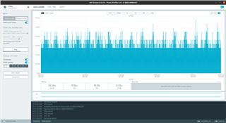
Then after connecting both devices to my computer, I opened the Power Profiler app in nRF Connect for Desktop, selected the PPK2 device, chose Ampere meter, clicked Start, and then I got a maximum current consumption of 0.58 µA. This can't be right for this example, the peaks for the advertisements should be much higher:

I confirmed that the iBeacon firmware is running: I can receive the advertisements on my phone with nRF Connect for Mobile.

How can I investigate what is going on?

  • Check the cable connection. It is most likely that the cables are not connected correctly or loose. 

  • I checked and double-checked again now, but all jumper cables are connected tightly, and I still get the same measurements.

  • Your connection is in Ampere mode. You may turn off the "Enable Power output" option and see if it works. 

  • I tried all suggestions, and after leaving this for a while I tried it again and I still see the same erroneous behaviour. Can someone from Nordic Semiconductor assist me?

  • Hi,

    Did you check with a multimeter that the SB40 is actually cut? I think it has to be either this, or the PPK is somehow broken, because it looks like there is no current flowing through the PPK. The 0.58 uA is probably just noise.

    If you connect the PPK they way you are doing, there might be some noise from the USB, so actually I would expect to see around 10 uA as the lowest base current. If you want to measure the lowest idle currents, I would suggest to use the PPK in source meter mode instead. So that the power is supplied from the PPK instead of the noisy USB port. With this setup the SB40 should be soldered (or just put a jumper on the header), so then you don't need to worry about cutting the SB40 properly.

    Connect the PPK VOUT and GND to the External supply header. Then flip the VExt->nRF switch to ON. Set the voltage output on the PPK to 3V. Leave the USB connected to power the debugger and the rest of the DK.

    And BTW, the "enable power output" button should be turned on, even in Ampere meter mode.

Related