
Hi , I got a problem when testing nrf53 qspi signal using a logic analyzer ,with a non-blocking init of qspi and a 4 Byte write , codes are below:
int main(void)
{
    uint32_t i;
    uint32_t err_code;

uint8_t base = 0x00;
if(!nrfx_is_word_aligned(m_buffer_tx)){

base = 0x02;
}

    LOG_INF(""
                 "QSPI write and read example using 24bit addressing mode");
    for (i = 0; i < QSPI_TEST_DATA_SIZE; ++i)
    {
        (m_buffer_tx+base)[i] = i;
    }
    for (i = 0; i < QSPI_TEST_DATA_SIZE; ++i)
    {
        (m_buffer_rx+base)[i] = 0x00;
    }


    nrfx_qspi_config_t config = NRFX_QSPI_DEFAULT_CONFIG(sck,cs,d0,d1,d2,d3);
    config.prot_if.writeoc = NRF_QSPI_WRITEOC_PP4IO ;
    config.prot_if.addrmode = NRF_QSPI_ADDRMODE_24BIT;


    err_code = nrfx_qspi_init(&config,NULL, NULL);

    LOG_INF("QSPI example started. %02X",err_code);


    err_code = nrfx_qspi_write((m_buffer_tx+base), 4, 0x38);


    }
I got a word align problem at first , solved it by adjusting the address at line 7
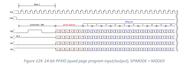
according to the ps the qspi out put on 4 wires should look like this :
however I got this from the logic analyzer connecting the nrf53 qspi pins I set :
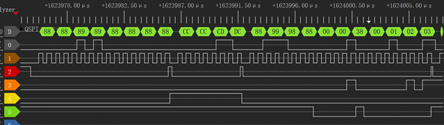
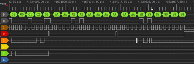
With 12 unexpected bytes before the command specified in ps , and 8 unexpected bytes after data . I looked deep into the api nrfx_qspi_write and found out it takes only the buffer address ,length and dst address, nothing relative to these unexpected bytes, with different inputs into the function I still got these .
We're using nrf53's qspi to communicate with a time-sensitive device , so these addtional bytes are intolerable , wonder if anyone can explain why they exist or how to remove them .
I'm using nrf connect sdk 1.5.1 , with a standard nrf53 dk

