nPM1100 - Connect ERR and CHG to LEDs and host at the same time

Hi,

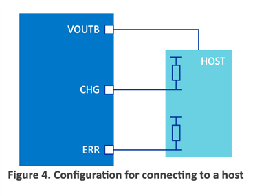
In the documentation for the nPM1100, in the section "Charging indication (CHG) and charging error indication (ERR)", there is a schematic for connecting ERR/CHG to LEDs, and there's a schematic for connecting to GPIO:
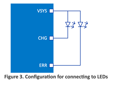
However, if you want a combination of the two (connected to LEDs AND to a host),  it says:

"To configure both LED indication and connection to a host, the GPIO input voltage range tolerance must be met, or an external circuit may be required. See Reference circuitry."

However, the reference circuitry does not include an example of this at all. All reference circuitry uses a LED-only setup. I also downloaded the zip with reference circuitry but it's the same 3 LED-only examples. 

For me this part is missing some details, and raises some questions. What would the circuit look like? What is the voltage of ERR/CHG? 

Is there an example of how to connect ERR and CHG to LEDS AND to an external microcontroller at the same time?

Thank you!

  • Hi,

    The ERR and CHG pins sink 5mA when activated, this combined with the LED will result in a voltage of VSYS minus the voltage drop of the LED to be present at the GPIO pin of the microcontroller. This voltage will in most cases not be low enough register as a low input, for the nRF52 series the maximum input low voltage is 0.3 x VDD. A resistor in series with the LED can possibly be used to increase the voltage drop such that the voltage present on the GPIO pin is low enough.

    One other possibility is to only connect the GPIO input to the CHG and ERR pin and use two other GPIO pins on the microcontroller to trigger the LEDs when CHG and ERR is activated.


    Is there an example of how to connect ERR and CHG to LEDS AND to an external microcontroller at the same time?

    We do unfortunately not have any example schematics where both LEDs and an external microcontroller is connected to the ERR and CHG pins.


    Best regards,

    Bendik  

Related