This post is older than 2 years and might not be relevant anymore
More Info: Consider searching for newer posts

recommended chip antenna, debugger for nRF52 based design

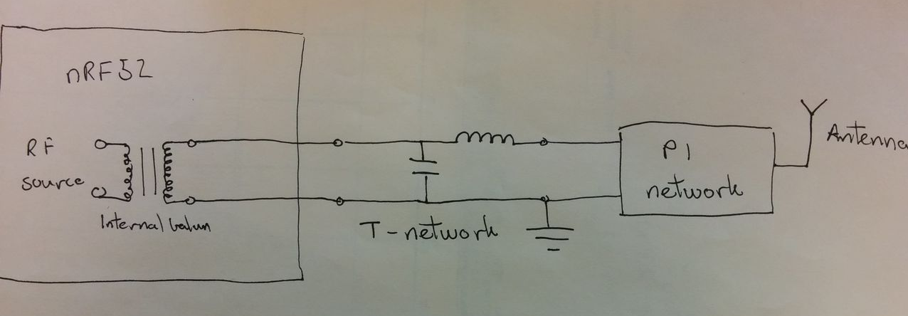
Is there any recommended chip antenna for NRF52 SoC? Any guideline on the antenna placement, designing the matching circuit etc? I assume for NRF52, no need for an external balun, since there is one integrated. Is that correct?

For debugging code on the chip, do I need to add a Segger J-Link port on my board?? Or is there any other way? Also do I need to buy an external debugger? (for eg like the TI www.ti.com/.../cc-debugger)

Parents
  • Hi,

    Any 2.4GHz chip antenna will work, select the one that fits your size, price and gain criteria. Be sure to place the chip antenna as specified in its datasheet.

    You do not need an external balun, however you will need a matching network between the antenna output and the antenna. See the general PCB design guidelines for 51, this is still highly relevant. Follow the reference circuitry.

    For a custom board you can add a J-Link port and debug using the debug out port of the development kit, see this blogpost for a setup overview.

    Role of the T-network:

    image description

    Internal balun: Matches the output of the chip to 50ohm

    T-Network: Removes unwanted RF characteristics, this can be noise on the harmonics(2nd, 3rd, 4th etc) unclean signal and other effects. The T-Network is often called an RF choke since it chokes out unwanted parts of your RF signal. If you remove this you may have problems with the regulatory tests.

    If you look at T-networks online you will see that they often consist of three components, our circuit may look like it breaks that rule. The trick is that for high frequency signals a short cable or PCB trace will acquire capacitive and inductive effects, so our third component is in the wiring. Have a look at the wikipedia article on transmission lines for more information.

    Pi-Network: Matches the antenna to 50ohm

    Best regards,

    Øyvind

Reply
  • Hi,

    Any 2.4GHz chip antenna will work, select the one that fits your size, price and gain criteria. Be sure to place the chip antenna as specified in its datasheet.

    You do not need an external balun, however you will need a matching network between the antenna output and the antenna. See the general PCB design guidelines for 51, this is still highly relevant. Follow the reference circuitry.

    For a custom board you can add a J-Link port and debug using the debug out port of the development kit, see this blogpost for a setup overview.

    Role of the T-network:

    image description

    Internal balun: Matches the output of the chip to 50ohm

    T-Network: Removes unwanted RF characteristics, this can be noise on the harmonics(2nd, 3rd, 4th etc) unclean signal and other effects. The T-Network is often called an RF choke since it chokes out unwanted parts of your RF signal. If you remove this you may have problems with the regulatory tests.

    If you look at T-networks online you will see that they often consist of three components, our circuit may look like it breaks that rule. The trick is that for high frequency signals a short cable or PCB trace will acquire capacitive and inductive effects, so our third component is in the wiring. Have a look at the wikipedia article on transmission lines for more information.

    Pi-Network: Matches the antenna to 50ohm

    Best regards,

    Øyvind

Children
Related