Board overlay for OV7670

Hi, 

I've trying to get the Omnivision OV7670 to work with the nRF52840-DK. I'm not completely sure whether I've configured it correctly. My pin assignments are adapted from the arduino tutorial: 
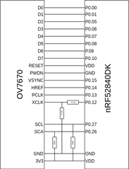
and my board overlay is as follows:

 &i2c0 {
	compatible = "nordic,nrf-twi";
	status = "okay";
	ov7670: ov7670@21 {
		compatible = "ovti_ov7670";
		reg = <0x21>;
		label = "ov7670";
		dio: dio {
   			data-gpios = <
						&gpio0 0 (GPIO_PULL_UP | GPIO_ACTIVE_LOW) /* D0 P1.01 */
						&gpio0 1 (GPIO_PULL_UP | GPIO_ACTIVE_LOW) /* D1 P1.02 */
						&gpio0 5 (GPIO_PULL_UP | GPIO_ACTIVE_LOW) /* D2 P1.03 */
						&gpio0 6 (GPIO_PULL_UP | GPIO_ACTIVE_LOW) /* D3 P1.04 */
						&gpio0 7 (GPIO_PULL_UP | GPIO_ACTIVE_LOW) /* D4 P1.05 */
						&gpio0 8 (GPIO_PULL_UP | GPIO_ACTIVE_LOW) /* D5 P1.06 */
						&gpio0 9 (GPIO_PULL_UP | GPIO_ACTIVE_LOW) /* D6 P1.07 */
						&gpio0 10 (GPIO_PULL_UP | GPIO_ACTIVE_LOW) /* D7 P1.08 */
					 >;
   			label = "dio";
   		};
		vsync: vsync {
   			gpios = < &gpio0 15 (GPIO_PULL_UP | GPIO_ACTIVE_LOW) >; /* GPIO P0.00 */
   			label = "vsync";
   		};
   		hsync: hsync {
   			gpios = < &gpio0 14 (GPIO_PULL_UP | GPIO_ACTIVE_LOW) >; /* GPIO P0.00 */
   			label = "hsync";
   		};
   		pclk: pclk {
   			gpios = < &gpio0 13 (GPIO_PULL_UP | GPIO_ACTIVE_LOW) >; /* GPIO P0.00 */
   			label = "pclk";
   		};
   		xclk: xclk {
   			gpios = < &gpio0 12 (GPIO_PULL_UP | GPIO_ACTIVE_LOW) >; /* GPIO P0.00 */
   			label = "xclk";
   		};
	};
};

Is this correct?

Parents
  • Hi,

    There are a few things there I find suspicious, but to be sure, could I see the .yaml file you added to zephyr/dts/bindings/video?

  • # Copyright (c) 2020, FrankLi Limited
    # SPDX-License-Identifier: Apache-2.0
    
    description: OV7670 CMOS video sensor
    
    compatible: "ovti_ov7670"
    
    properties:
       reg:
          type: array
          required: true
       reset-gpios:
          type: phandle-array
          required: false
          description: |
            The RESETn pin is asserted to disable the sensor causing a hard
            reset.  The sensor receives this as an active-low signal.
    
    include: i2c-device.yaml

  • Ok, so first of all use the comma in the compatible string and in the name of the .yaml file, like the other bindings do. It will be converted to an underline in the devicetree.

    Secondly, anything you want to be recognized in the .overlay file must be in the .yaml file. So all those gpios must be added. Also the formatting of the gpios in the .overlay file is a little off. The "reg" property is defined in i2c-device.yaml, so there is no need to define it again. Try these files instead:

    description: OV7670 CMOS video sensor
    
    compatible: "ovti,ov7670"
    
    properties:
        reset-gpios:
          type: phandle-array
          required: false
          description: |
            The RESETn pin is asserted to disable the sensor causing a hard
            reset.  The sensor receives this as an active-low signal.
        
        data-gpios:
          type: phandle-array
          required: false
        
        vsync-gpios:
          type: phandle-array
          required: false
        
        hsync-gpios:
          type: phandle-array
          required: false
        
        pclk-gpios:
          type: phandle-array
          required: false
        
        xclk-gpios:
          type: phandle-array
          required: false
    
    include: i2c-device.yaml

    &i2c0 {
    	compatible = "nordic,nrf-twim";
    	status = "okay";
    	ov7670@21 {
    		compatible = "ovti,ov7670";
    		reg = <0x21>;
    		label = "ov7670";
    
    		data-gpios = <&gpio0 0 (GPIO_PULL_UP | GPIO_ACTIVE_LOW)>,
    			  <&gpio0 1 (GPIO_PULL_UP | GPIO_ACTIVE_LOW)>,
    			  <&gpio0 5 (GPIO_PULL_UP | GPIO_ACTIVE_LOW)>,
    			  <&gpio0 6 (GPIO_PULL_UP | GPIO_ACTIVE_LOW)>,
    			  <&gpio0 7 (GPIO_PULL_UP | GPIO_ACTIVE_LOW)>,
    			  <&gpio0 8 (GPIO_PULL_UP | GPIO_ACTIVE_LOW)>,
    			  <&gpio0 9 (GPIO_PULL_UP | GPIO_ACTIVE_LOW)>,
    			  <&gpio0 10 (GPIO_PULL_UP | GPIO_ACTIVE_LOW)>;       
    
    		vsync-gpios = < &gpio0 15 (GPIO_PULL_UP | GPIO_ACTIVE_LOW) >;
    
       		hsync-gpios = < &gpio0 14 (GPIO_PULL_UP | GPIO_ACTIVE_LOW) >;
    
       		pclk-gpios = < &gpio0 13 (GPIO_PULL_UP | GPIO_ACTIVE_LOW) >;
    
       		xclk-gpios = < &gpio0 12 (GPIO_PULL_UP | GPIO_ACTIVE_LOW) >;
    	};
    };

  • Ok, I was a bit confused about the .yaml file since the ov7725 yaml file didn't have all those GPIO's. I've adjusted the files but when I run this code, I get a dev==NULL:

    void main(void)
    {
        const struct device *dev = device_get_binding("ov7670");
        if (dev == NULL) {
            printk("Error: Could not get ov7670 device binding\n");
        }
    
    }

  • I took a quick look at the datasheet, and the ov7725 seems to support a 2-wire interface. It might be set up to only get that from the board, and the rest of its inputs from somewhere else? But I only took a glance, so I have no idea how the modules work.

    The dev==NULL is expected. In your ov7670.c driver file, try adding "return 0;" at the beginning of the ov7670_init() function. (not ov7670_init_0() )
    This is just to test where it fails.

  • Seems like it doesn't make it to ov7670_init().

Reply Children
Related
