This discussion has been locked.
You can no longer post new replies to this discussion. If you have a question you can start a new discussion

case about the calculation formula of 32MHz crystal oscillator offset adjustment

Hi,

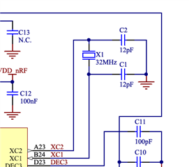
1. Configuration: Recommended crystal oscillator circuit: C1 = 12pF C2 = 12pF

2. Configuration: Crystal oscillator circuit used by the customer: C1 = 10pF C2 = 10pF

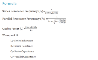
3. What formula can be used to calculate the theoretical frequency deviation: for example, the theoretical frequency deviation between configuration 1 and configuration 2

Thank you for all your assistance.
Kind regards,
Peter.Min

Parents
  • Hello Peter,

    Thanks for your query.

    The deviation in frequency depends on the crystal and it's pulling capabilities.

    On nRF52, an external 32 MHz crystal is mandatory, and an external 32 kHz crystal is optional. Because, It will give lower average current consumption than using the RC oscillator, at the expense of cost and board space. 

    The way ( https://infocenter.nordicsemi.com/index.jsp?topic=%2Fps_nrf52840%2Fclock.html&cp=4_0_0_4_3_3_1&anchor=unique_106537914 ) of finding the value of C1 and C2 is- ( it should be same values)

    C1 = C2 = 2Cl - C_pcb - C_pin

    Cl: Load capacitance of the crystal (found in the crystal datasheet) (it should be below 12 pf)

    C_pcb + C_pin is approximately 4 pF. The general formula to find resonance frequency for series and parallel capacitance is -

    We can see from the quartz crystal equivalent circuit where is the inductance. To get the value (theoretical) of frequency from the above formula you can find the value of L from your datasheet (if there is any). For both parameters when you have the frequency, you will know the deviation theoretically.  

    One practical thing is that you have to measure the central frequency of the carrier. For example: measuring the frequency of the 32 MHz crystal should be done by measuring the frequency error of an unmodulated carrier transmitted by the radio. If the carrier frequency of the radio is within the specifications, the 32 MHz crystal is also within the specifications. Therefore , when choosing a crystal it is important to set it within the specifications (Nordic Semiconductor Infocenter). In addition, probing of the crystal should be done carefully otherwise the frequency of crystal will drift; because probe will create capacitance and that will change the total values of the load capacitors. 

    Here is a link from our earlier blog post about general PCB design which may be a relevant reading for you. General PCB design guidelines for nRF52 series - Hardware design, test and measurement - nRF5 SDK guides - Nordic DevZone (nordicsemi.com) 

    I hope it helps. Please let us know if you further queries. 

    have a nice weekend.

    Best Regards,

    Kazi Afroza Sultana

Reply
  • Hello Peter,

    Thanks for your query.

    The deviation in frequency depends on the crystal and it's pulling capabilities.

    On nRF52, an external 32 MHz crystal is mandatory, and an external 32 kHz crystal is optional. Because, It will give lower average current consumption than using the RC oscillator, at the expense of cost and board space. 

    The way ( https://infocenter.nordicsemi.com/index.jsp?topic=%2Fps_nrf52840%2Fclock.html&cp=4_0_0_4_3_3_1&anchor=unique_106537914 ) of finding the value of C1 and C2 is- ( it should be same values)

    C1 = C2 = 2Cl - C_pcb - C_pin

    Cl: Load capacitance of the crystal (found in the crystal datasheet) (it should be below 12 pf)

    C_pcb + C_pin is approximately 4 pF. The general formula to find resonance frequency for series and parallel capacitance is -

    We can see from the quartz crystal equivalent circuit where is the inductance. To get the value (theoretical) of frequency from the above formula you can find the value of L from your datasheet (if there is any). For both parameters when you have the frequency, you will know the deviation theoretically.  

    One practical thing is that you have to measure the central frequency of the carrier. For example: measuring the frequency of the 32 MHz crystal should be done by measuring the frequency error of an unmodulated carrier transmitted by the radio. If the carrier frequency of the radio is within the specifications, the 32 MHz crystal is also within the specifications. Therefore , when choosing a crystal it is important to set it within the specifications (Nordic Semiconductor Infocenter). In addition, probing of the crystal should be done carefully otherwise the frequency of crystal will drift; because probe will create capacitance and that will change the total values of the load capacitors. 

    Here is a link from our earlier blog post about general PCB design which may be a relevant reading for you. General PCB design guidelines for nRF52 series - Hardware design, test and measurement - nRF5 SDK guides - Nordic DevZone (nordicsemi.com) 

    I hope it helps. Please let us know if you further queries. 

    have a nice weekend.

    Best Regards,

    Kazi Afroza Sultana

Children
Related