This discussion has been locked.
You can no longer post new replies to this discussion. If you have a question you can start a new discussion

NRF523840 Standard Drive, Output Current, and LEDs

Hi All,

I feel like this question/topic has probably been discussed ad nauseum, but I feel like I'm not confident in the conclusion I'm drawing from other posts I've seen. Please forgive me if there is a clear answer to this floating somewhere around =(.

As the subject title would imply, I'm trying to wrap my head around GPIO Drive and the amount of output current, and driving an LED.

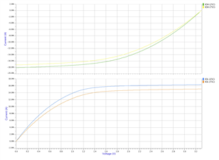
From my understanding, with "standard drive", a GPIO pin should be able to source 0.5mA. However, if we look at the electrical specification for the NRF52840, I see the following: 

So, I guess my first question is... what is the true source current limit for standard drive? 

My follow up question then is whether or not the GPIO pin will limit the current itself. So just as an example... If I had:

3.0V GPIO Output ------ 60ohm R -------- 1.8Vf LED ------ GND

In this setup, I'd expect 20mA of current to flow, however because GPIO is set to standard drive... will it just limit itself to the max source-able current? 

  • The GPIO will limit the current due to the internal resistance in the GPIO output driver. The current that's stated as max current for standard and high drive it when you need to have a guaranteed voltage on the output. If you draw more current the voltage will be lower or higher depending if the output is high or low. 

    It's like having a second, internal, resistor in series with the LED of about 50 ohm in standard drive and 20 ohm in high drive. 

  • Thanks for the reply ketiljo.

    So the 0.5mA for standard drive implies that I can reliably have Vdd when I'm trying to source 0.5mA. However if I were to pull more current, I can expect to see the 1mA-4mA however down to Vdd - 0.4V?

    I think it's becoming more clear to me now. The source of the "internal resistance" is from the (I assume) FETs in the microcontroller which gate the output voltage. Right? 

  • The voltage drop vs. current curve in high drive looks like this:

    Depending if you're sinking or sourcing.

    Let's say you source 4 mA to a load connected between the pin and ground. The voltage drop will be 0.2 V, so the voltage on the pin will be VDD - 0.2 V, 

    You want to use high drive when you're driving a LED directly.

  • This makes sense. Where can I find these graphs?

  • They're not in the datasheet. This is simulated.

Related