PPI and timers


Hello
I am learning how to connect timers with gpio via PPI, i working on nrf52832dk.

So far I have connected the RTC 0 alarm channel to the LED no.3 (pin no.19) and its state changes every time the timer is called.

I tried to do the same with timer 1 and LED4 (pin no.20) , unfortunately this connection won't work.

I am enclosing the code that theoretically should work, can anyone check this problem?


#include <zephyr.h>
#include <debug/ppi_trace.h>
#include <drivers/counter.h>
#include <hal/nrf_rtc.h>
#include <hal/nrf_clock.h>
#include <hal/nrf_timer.h>
#include <nrfx_timer.h>
#include <device.h>
#include <logging/log.h>

LOG_MODULE_REGISTER(app);

#define ALARM_PERIOD_US 1000 * 1000
#define RTC NRF_RTC2
#define TIMER NRF_TIMER1

#define RTC_LABEL DT_LABEL(DT_NODELABEL(rtc2))
#define TIMER_LABEL DT_LABEL(DT_NODELABEL(timer1))

static void alarm_callback(const struct device *dev, uint8_t chan_id, uint32_t ticks,
						   void *user_data);

static void timer_callback(const struct device *dev, uint8_t chan_id, uint32_t ticks,
						   void *user_data);

static struct counter_alarm_cfg RTC_alarm_cfg = {
	.callback = alarm_callback,
	.flags = COUNTER_ALARM_CFG_ABSOLUTE,
};

static struct counter_alarm_cfg TIM0_alarm_cfg = {
	.callback = timer_callback,
	.flags = 0, //?
};

static void ppi_trace_pin_setup(uint32_t pin, uint32_t evt)
{
	void *handle;

	handle = ppi_trace_config(pin, evt);
	__ASSERT(handle != NULL,
			 "Failed to initialize trace pin, no PPI or GPIOTE resources?");

	ppi_trace_enable(handle);
}


static void ppi_trace_setup(void)
{
	ppi_trace_pin_setup(19,
						nrf_rtc_event_address_get(RTC, NRF_RTC_EVENT_COMPARE_0));
	

	ppi_trace_pin_setup(20, nrf_timer_event_address_get(TIMER, NRF_TIMER_EVENT_COMPARE1));

	LOG_INF("PPI trace setup done.");
}

static void alarm_callback(const struct device *dev, uint8_t chan_id,
						   uint32_t ticks, void *user_data)
{
	int err;
	uint32_t alarm_cnt = (uint32_t)user_data + 1;

	RTC_alarm_cfg.ticks = ticks + counter_us_to_ticks(dev, ALARM_PERIOD_US);
	RTC_alarm_cfg.user_data = (void *)alarm_cnt;
	LOG_INF("alarm_callback");
	err = counter_set_channel_alarm(dev, 0, &RTC_alarm_cfg);
	__ASSERT_NO_MSG(err == 0);
	(void)err;
}

static void timer_callback(const struct device *dev, uint8_t chan_id,
						   uint32_t ticks, void *user_data)
{
	int err;
	uint32_t alarm_cnt = (uint32_t)user_data + 1;

	TIM0_alarm_cfg.ticks = counter_us_to_ticks(dev, ALARM_PERIOD_US/2);
	TIM0_alarm_cfg.user_data = (void *)alarm_cnt;
	LOG_INF("timer_callback %d ",TIM0_alarm_cfg.ticks);
	err = counter_set_channel_alarm(dev, 1, &TIM0_alarm_cfg);
	__ASSERT_NO_MSG(err == 0);
	(void)err;
}

static void counter_setup(void)
{
	{
		int err;
		const struct device *dev = device_get_binding(RTC_LABEL);

		__ASSERT(dev, "Sample cannot run on this board.");

		RTC_alarm_cfg.ticks = counter_us_to_ticks(dev, ALARM_PERIOD_US);
		err = counter_set_channel_alarm(dev, 0, &RTC_alarm_cfg);
		__ASSERT_NO_MSG(err == 0);

		err = counter_start(dev);
		__ASSERT_NO_MSG(err == 0);
	}
	{
		int err;
		const struct device *dev = device_get_binding(TIMER_LABEL);

		__ASSERT(dev, "Sample cannot run on this board.");

		TIM0_alarm_cfg.ticks = counter_us_to_ticks(dev, ALARM_PERIOD_US);

		err = counter_set_channel_alarm(dev, 1, &TIM0_alarm_cfg);
		__ASSERT_NO_MSG(err == 0);

		 err = counter_start(dev);
		__ASSERT_NO_MSG(err == 0);
	}
}

void main(void)
{
	ppi_trace_setup();
	counter_setup();

	while (1)
	{
		k_msleep(1000);
	}
}

Parents Reply Children
  • I believe i found problem in driver, but i may be wrong. 

    My code:

    #include <zephyr.h>
    #include <debug/ppi_trace.h>
    #include <drivers/counter.h>
    #include <hal/nrf_rtc.h>
    #include <hal/nrf_clock.h>
    #include <hal/nrf_timer.h>
    #include <nrfx_timer.h>
    #include <device.h>
    #include <logging/log.h>
    
    LOG_MODULE_REGISTER(app);
    #define ALARM_PERIOD_US 1000 * 1000
    #define TIMER NRF_TIMER1
    #define TIMER_LABEL DT_LABEL(DT_NODELABEL(timer1))
    
    static void timer_callback(const struct device *dev, uint8_t chan_id, uint32_t ticks,
    						   void *user_data);
    
    static struct counter_alarm_cfg TIM0_alarm_cfg = {
    	.callback = timer_callback,
    	.flags = 0, //?
    };
    
    static void ppi_trace_pin_setup(uint32_t pin, uint32_t evt)
    {
    	void *handle;
    
    	handle = ppi_trace_config(pin, evt);
    	__ASSERT(handle != NULL,
    			 "Failed to initialize trace pin, no PPI or GPIOTE resources?");
    
    	ppi_trace_enable(handle);
    }
    
    static void ppi_trace_setup(void)
    {
    	ppi_trace_pin_setup(19, nrf_timer_event_address_get(TIMER, NRF_TIMER_EVENT_COMPARE0));
    
    	ppi_trace_pin_setup(20, nrf_timer_event_address_get(TIMER, NRF_TIMER_EVENT_COMPARE2));
    
    	LOG_INF("PPI trace setup done.");
    }
    
    static void timer_callback(const struct device *dev, uint8_t chan_id,
    						   uint32_t ticks, void *user_data)
    {
    	int err;
    	uint32_t alarm_cnt = (uint32_t)user_data + 1;
    
    	TIM0_alarm_cfg.ticks = counter_us_to_ticks(dev, ALARM_PERIOD_US );
    	TIM0_alarm_cfg.user_data = (void *)alarm_cnt;
    	LOG_INF("timer_callback %d ", TIM0_alarm_cfg.ticks);
    	err = counter_set_channel_alarm(dev, 0, &TIM0_alarm_cfg);
    	__ASSERT_NO_MSG(err == 0);
    	(void)err;
    }
    
    static void counter_setup(void)
    {
    	int err;
    	const struct device *dev = device_get_binding(TIMER_LABEL);
    
    	__ASSERT(dev, "Sample cannot run on this board.");
    
    	TIM0_alarm_cfg.ticks = counter_us_to_ticks(dev, ALARM_PERIOD_US);
    
    	err = counter_set_channel_alarm(dev, 0, &TIM0_alarm_cfg);
    	__ASSERT_NO_MSG(err == 0);
    
    	err = counter_start(dev);
    	__ASSERT_NO_MSG(err == 0);
    }
    
    void main(void)
    {
    	ppi_trace_setup();
    	counter_setup();
    
    	while (1)
    	{
    		k_msleep(1000);
    	}
    }
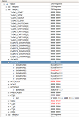
    

    Description: 

    I working on nrf52832 dk.

    The problem is with the wrong selection of the timer alarm channel. I call function which should use channel 0 timer 1

    counter_set_channel_alarm(dev_tim, NRF_TIMER_CC_CHANNEL0, &TIM0_alarm_cfg);

    But the driver has assigned an alarm interrupt on channel 2, you can see it in the CPU registers. ( active interrupt 2 not 0)

  • Hi

    What do you get if you run the counter_get_num_of_channels(..) function?

    It is not necessarily a direct mapping between the counter channel ID and the CC register value. The counter driver is probably using some CC registers for other purposes, so that it is not able to use all of them for registering alarms. 

    Best regards
    Torbjørn

  • uint32_t adr = counter_get_num_of_channels(timer_dev);

    adr = 0x02
  • Hi 

    That makes sense. TIMER1 in the nRF52832 has 4 CC registers (CC0-CC3), so if CC2 is used for channel ID 0 and CC3 for channel ID 1, then there are only CC registers available for 2 channels. 

    If you want more direct control of the timer and its registers you can use the nrfx_timer library instead. 

    Best regards
    Torbjørn

Related