

Hey,
Our custom board based on the reference circuitry in "Product Specification v1.2":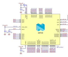
We have been using the B0 revision of nRF9160 so far. Now we are planning on switching to B1 and I noticed that the reference circuitry has changed in the latest specification:
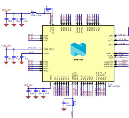
The newer specification has 6 more capacitors, 1 more resistor and a ferrite bead, which would take up a significant amount of space on our tiny board. Are all of these mandatory when using the B1 revision or is it possible to use B1 on our existing design which has worked reliably with B0?
We also have some additional caps and a ferrite bead on the VCC-line:
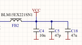
I'm not entirely sure why these components were placed on the design as the person who made the original design is no longer working for us. On the PCB they are located close to the VDD-pin (102) of nRF9160. Do you think these combined with the 4.7µF caps in the older reference design are sufficient for B1?
There's also a resistor and cap on the nRESET pin on the newer reference design. Are these necessary with B1 or does it have something to do with the design of nRF9160DK?
Thanks in advance!
