ADXL362 with nRF9160 DK not working

Hello Nordic Support,

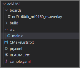
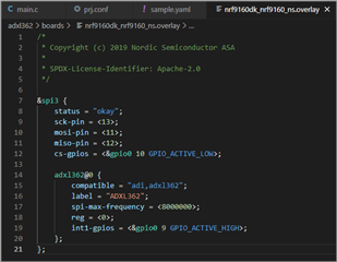
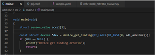
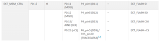
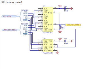
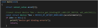
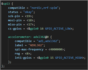
I started with a sensor sample project for ADXL362 Three Axis Accelerometer (https://github.com/zephyrproject-rtos/zephyr/tree/main/samples/sensor/adxl362) and connected to my nRF9160DK board. I used the same SPI lines that external memory is used on nRF9160DK board but a different Chip Select IO for the sensor. I am able to compile the code successfully but I am not able to bind the sensor. Can you please review and suggest what could be an issue?
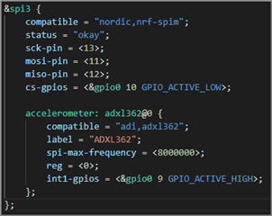
Project:

adxl362.zip

  • Hello, 

    Have you verified that the board controller is configured correctly as the pins configured are controlled by this device.


    More information about the board controller can be found here

    Kind regards,
    Øyvind

  • Hello,

    I resolved the sensor binding error. The device binding method used in the ADXL362 zephyr sensor sample code is not supported for ncs 1.7.0.

    I modified overlay file as below:

    And the device binding method changed as below:

    With these changes, I am not getting binding error any more but sensor data read is not working. Looking at the SPI signal with a logic analyzer, the signals that master is outputting don't seem to be correct for sensor to respond.

    This is the SPI trace with nRF9160 DK connected to ADXL362. The SPI clock stops several times while reading data.

    This is the trace of the same sensor board connected to a arduino board:

    Any suggestions where I can look for potential problem?

  • Did you configure the board control to enable ext_mem_ctrl? 

  • I do not want to change board controller firmware at this point, else I dont know what else will break. I changed my pin assignments to other pins that are not shared with board controller. But I am seeing the same SPI protocol waveform. The clock always stops  for about 30us after sending first 2 bytes (command).

    The other differences I can see between nRF91 DK SPI and Arduino board SPI waveform are:

    1. The MOSI io default state is low for nRF91 DK vs high for Arduino board.

    2. When master clocks to read 8 bytes out, the MOSI io stays high entire time in nRF91 DK vs stay low during bytes read and toggle between data bytes for Arduino board.

    3. The clocks for 8 data bytes read is contiguous without any break between each bytes read for nRF91 DK vs 1us idle between bytes reads for Arduino board.

    It definitely looks like some kind of SPI configuration or SPI driver level issue. Need help urgently please.

  • I sort of found the problem. The looked in to the adxl362 drivers provided in ncs v1.7.0 zephyr drivers and as per the "adxl362_init()" if sensor do not respond to Part ID read command <0B><02> with <F2> then no further configuration is done on the sensor leaving sensor in standby mode. So further read of XYZ channels will not read any data. For some reason I am always getting <F0>  instead of <F2> for Part ID command. I dropped SPI clock rate top 1 MHZ and just in case signals has distortion at higher frequency. The sensor board is connected directly on the header of the nRF91DK board without any wires and signals are clean and square. But still Part ID read command is returning incorrect ID.

    I modified zephyr adxl362 driver (just for debugging) to by pass return on Part ID read error and let driver go ahead with sensor configuration. With that I am now able to read XYZ channels each time although channel data are noisy.

    One thing I am finding very odd and not able to remove is the clock delay between command byte and data read byte. Delay is about 16us at 1Mhz SPI clock and 27us at 4Mhz SPI clock. I am not sure if this is causing the incorrect Part ID read, but I would like to minimize it if possible. It looks like delay of SPI peripheral in nRF91 when it switch write to read mode. Any idea how to reduce this delay?

Related