This discussion has been locked.
You can no longer post new replies to this discussion. If you have a question you can start a new discussion

Obtaining less then 50uA with 52840 dongle and PPKII

Hi,

after fixing a missing ground in my setup (see devzone.nordicsemi.com/.../interaction-jlink-and-power-profiler-ppkii) I have not been able to get less than 50uA of idle current on the 52840 dongle, when it should be around 2-3 uA. My main.c is

#include <zephyr.h>
#define SLEEP_TIME_MS   10000
void main(void)
{
	while (1) {
		k_msleep(SLEEP_TIME_MS);
	}
}

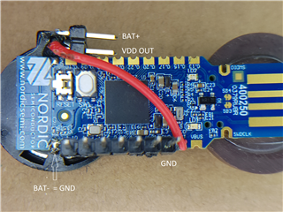
and I use CONFIG_SERIAL=n in prj.conf. I guess I have read almost all posts here on the forum about low power modes, but I could not find anything similar. I have tried the PPKII in source and in ampere meter mode (using a 3V battery), the USB is not connected and power is supplied using VDD Out pin with SB2 cut and SB1 soldered. I have measured with the debugger disconnected and done a power reset after disconnecting. All with the same result, around 50uA of mean current at 3V.

When using source mode on the PPKII I can drop the voltage to 1.9V and then I get around 15uA. Why should the current drop with the supplied voltage?

From the schematics the 52840 dongle does not have any passive elements which could source current (apart from the leds and , so I'd suspect power consumption coming from the SoC itself. But I have even measured 50uA @ 3V using

pm_power_state_force((struct pm_state_info){PM_STATE_SOFT_OFF, 0, 0});

which should be the lowest power mode possible. I am really stuck with this, any help appreciated!

Parents
  • Hi

    How exactly are you connecting the PPK2 to the Dongle? I agree with Stian that you should be able to get down (or at least close to) 2-3uA. Maybe you could upload a high resolution picture so we can take a look at how the PPK and Dongle is connected.

    Best regards,

    Simon

  • Here you go! When measuring with the PPK2 as source I connect PPK2-VOUT to the "VDD OUT" pin on top (which is connected by the red cable to the dongle's VDD-OUT) and PPK2-GND to the GND pin on the lower right. When using amperemeter mode, I connect PPK2-VIN to BAT+ (which is connected to the battery below), PPK-VOUT to the upper VDD OUT pin and PPK-GND to the lower right GND. The battery - is soldered to the GND pin on the lower left.

    Normal operating mode is simply to shorten BAT+ and VDD OUT. The cell gives 3.020V.

    In case you have doubts about my soldering skills - which I do have :) - I have also connected PPK2-VOUT directly to the VBUS pin and PPK2-GND to the GND next to it on another unit which does not have the SB2 cut  and SB1 soldered. In this case I got 35uA at 5V.

Reply
  • Here you go! When measuring with the PPK2 as source I connect PPK2-VOUT to the "VDD OUT" pin on top (which is connected by the red cable to the dongle's VDD-OUT) and PPK2-GND to the GND pin on the lower right. When using amperemeter mode, I connect PPK2-VIN to BAT+ (which is connected to the battery below), PPK-VOUT to the upper VDD OUT pin and PPK-GND to the lower right GND. The battery - is soldered to the GND pin on the lower left.

    Normal operating mode is simply to shorten BAT+ and VDD OUT. The cell gives 3.020V.

    In case you have doubts about my soldering skills - which I do have :) - I have also connected PPK2-VOUT directly to the VBUS pin and PPK2-GND to the GND next to it on another unit which does not have the SB2 cut  and SB1 soldered. In this case I got 35uA at 5V.

Children
No Data
Related