This discussion has been locked.
You can no longer post new replies to this discussion. If you have a question you can start a new discussion

Energy Buffering for cr2032 battery

Hello,

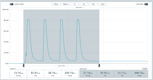
I’m designing a custom nrf52832 device and i came across an issue with energy buffering. I am using inside of the device the battery CR2032, SoC nrf52832 and two proximity sensors VCNL3040 ( https://www.vishay.com/docs/84917/vcnl3040.pdf ). Those sensors have pulse current up to 200mA for a few mili seconds (as you can see on attached image), but the battery is rated only for 0.2 mA load. The problem is, those hight current pulses cause capacity drop and voltage drop of the battery, and on the end also cause hard restart of the device.

I was wondering, if you have some example design for energy buffering that would be suitable for my use case.

One more important thing is, the device is designed for long battery life, and most of the time is in sleep mode, therefore has the average power consumption of around 5 uA.

Thank you.

Best Regards,
Tomas

Parents
  • Hi Jared, 

    As you say, I was thinking of doing a hybrid solution, where I would gradually charge the capacitor with a low current (max 0.2 mA) so the battery would not be stressed as much.

    I don't have much experience in this field either. Can you recommend me any alternative electronic forum where someone might have more insight in this type of issues? 

    Best regards,
    Tomas

Reply
  • Hi Jared, 

    As you say, I was thinking of doing a hybrid solution, where I would gradually charge the capacitor with a low current (max 0.2 mA) so the battery would not be stressed as much.

    I don't have much experience in this field either. Can you recommend me any alternative electronic forum where someone might have more insight in this type of issues? 

    Best regards,
    Tomas

Children
  • The most efficient solution is to throw away schottky diodes, which are too inefficient - 300mV drop on a 3 volt CR2032 loses 10% of battery power over the battery lifetime.

    Instead use an Ideal Diode from the coin cell to a local capacitor bank say 100uF (ceramics not Tantalum or SuperCap, derate capacitor voltage by a factor of x2 to avoid loss of capacity, so 100uF 10Volt or 6.3 volt ceramic).. Loads must be connected directly to the coin cell with separate capacitor storage, ceramics say 150uF 10 volt though 6.3 volt is ok. Do not source load power from the MPU pins to avoid draining the nRF52 capacitor bank. Active-low drivers can use the port pin, active-high should be buffered by interface powered from coin cell not nRF52 VCC.

    Use PWM to drive loads such as LEDs or mini speakers; tune the PWM to protect the coin cell. Massive voltage drops on the coin cell can be tolerated since the nRF52 is isolated with the local VCC supply. Connect the proximity sensors direct to the battery.

Related