NRF9160 and LR1110 on SPI

Hi, I accidentally marked one of my own replies as the answer.

I'm trying to interface LR1110 (Dev Board) with NRF9160 DK using SPI. I have been working on this for a couple of weeks, explored almost the whole devzone, learned a lot, you guys are wonderful.

Semtech provides the driver for LR1110 here.

I am trying to write lr1110_hal.c for SPI communication but not getting a response from LR1110, when I tried to connect the LR1110 board with Arduino, Arduino is getting a response. 

I observed the SPI signals on an oscilloscope, SCK is giving perfect clock, MOSI is sending Data, but Chip Select is not toggling with SPI sends. Please check my codes and configurations for some Errors, secondly, I'm getting ERROR: RFX_ERROR_INVALID_STATE in nrfx_spim_init() call.

Below is my nrf9160dk_nrf9160ns.overlay file

&spi3 {
	compatible = "nordic,nrf-spim";
	status = "okay";
	sck-pin = <13>;
	mosi-pin = <11>;
	miso-pin = <12>;
	cs-gpios = <&gpio0 21 1>;
	clock-frequency = <4000000>;
};

Below is my prj.conf

CONFIG_TRUSTED_EXECUTION_NONSECURE=y

# General config
CONFIG_NEWLIB_LIBC=y
CONFIG_NEWLIB_LIBC_FLOAT_PRINTF=y
CONFIG_ASSERT=y
CONFIG_REBOOT=y
CONFIG_RESET_ON_FATAL_ERROR=n

# Logging
CONFIG_UART_CONSOLE=y
CONFIG_LOG=y
CONFIG_LOG_IMMEDIATE=y

# DK - Used for buttons and LEDs in UI module.
CONFIG_DK_LIBRARY_INVERT_LEDS=n

CONFIG_SHELL=y

CONFIG_SERIAL=y
CONFIG_GPIO=y

# SPI
CONFIG_SPI=y
CONFIG_SPI_3=y
CONFIG_SPI_NRFX=y
CONFIG_NRFX_SPIM=y
CONFIG_NRFX_SPIM3=y

Below is my lr1110_hal.c file

#include <zephyr.h>
#include <device.h>
#include <logging/log.h>
#include <nrfx_spim.h>
#include <drivers/nrfx_errors.h>
#include "lr1110_hal.h"

#define LR1110_NODE			DT_ALIAS(lr1110alias)
#define SPIM_DRV_NAME			"SPI_3"

#define NRFX_CUSTOM_ERROR_CODES 0 //used in nrfx_errors.h

#define NRFX_SPIM_SCK_PIN  (13)
#define NRFX_SPIM_MOSI_PIN (11)
#define NRFX_SPIM_MISO_PIN (12)
#define NRFX_SPIM_SS_PIN   (21)

static uint8_t       m_tx_buf[10] = {0x0, 0x0, 0x0, 0x0, 0x0, 0x0, 0x0, 0x0, 0x0, 0x0 };           /**< TX buffer. */
static uint8_t       m_rx_buf[100];  /**< RX buffer. */
static const uint8_t m_length = sizeof(m_tx_buf);        /**< Transfer length. */

#define SPI_INSTANCE  3 
static const nrfx_spim_t spi = NRFX_SPIM_INSTANCE(SPI_INSTANCE);
#define SPIM1_IRQn UARTE3_SPIM3_SPIS3_TWIM3_TWIS3_IRQn
#define ISR_PRIORITY 5

static volatile bool spi_xfer_done = true;

void spim_event_handler(nrfx_spim_evt_t const * p_event, void * p_context)
{
   spi_xfer_done = true;
   if (m_rx_buf[0] != 0)
   {
       printk("Received in hex: ");
		for (int i = 0; i < strlen((const char *)m_rx_buf); i++)
			printk("%x ", m_rx_buf[i]);
		printk("\n");
		printk("ascii: %s\n", m_rx_buf);
   }	
}

void setup_spim(void)
{
   	nrfx_spim_config_t spi_config = 	NRFX_SPIM_DEFAULT_CONFIG(
		NRFX_SPIM_SCK_PIN, 
		NRFX_SPIM_MOSI_PIN,
		NRFX_SPIM_MISO_PIN,
		NRFX_SPIM_SS_PIN);
   	printk("Setting SPI\n");
	//uint32_t err = nrfx_spim_init(&spi, &spi_config, spim_event_handler, NULL);
	uint32_t err = nrfx_spim_init(&spi, &spi_config, NULL, NULL);
	if (err == NRFX_ERROR_INVALID_STATE) {
		printk("nrfx INIT NRFX_ERROR_INVALID_STATE\n");
		return;
	}
	if (err == NRFX_ERROR_BUSY) {
		printk("nrfx INIT NRFX_ERROR_BUSY\n");
		return;
	}
	if (err == NRFX_ERROR_NOT_SUPPORTED) {
		printk("nrfx INIT NRFX_ERROR_NOT_SUPPORTED\n");
		return;
	}
	if (err != NRFX_SUCCESS) {
		printk("nrfx INIT err: %d\n", err);
		return;
	}
   	printk("SPI SET\n");
	/* Zephyr IRQ wrapper, corresponds to NVIC_* functions */
	//IRQ_CONNECT(SPIM1_IRQn, ISR_PRIORITY, nrfx_spim_3_irq_handler, NULL, 0);
}

void test_SPIM(void)
{
	memset(m_rx_buf, 0, m_length);
	memset(m_tx_buf, 0, m_length);
	m_tx_buf[0] = 0x01;
	m_tx_buf[1] = 0x01;
	m_tx_buf[2] = 0x00;
	m_tx_buf[3] = 0x00;
	m_tx_buf[4] = 0x00;
	m_tx_buf[5] = 0x00;
	m_tx_buf[6] = 0x00;


	nrfx_spim_xfer_desc_t xfer_desc = NRFX_SPIM_XFER_TRX(m_tx_buf, 7, m_rx_buf, 7);
	memset(m_rx_buf, 0, m_length);
	uint32_t ret = nrfx_spim_xfer(&spi, &xfer_desc, 0);
	for (int i = 0; i < 7; i++)
		printk("%x ", m_rx_buf[i]);
	printk("\n");
}

lr1110_hal_status_t lr1110_hal_reset( const void* context ) 
{
	return LR1110_HAL_STATUS_OK;
}

lr1110_hal_status_t lr1110_hal_wakeup( const void* context ) 
{
	return LR1110_HAL_STATUS_OK;
}

Below is my main.c

#include <zephyr.h>
#include <stdio.h>
#include <string.h>
#include <stdlib.h>
#include <sys/printk.h>
#include <devicetree.h>
#include <drivers/gpio.h>
#include "lr1110_hal.h"
#include "lr1110_wifi.h"


lr1110_hal_status_t lr_status;

void main(void)
{
    printk("SPIM Example\n");	
	
	setup_spim();
		
	while (1) {
		test_SPIM();
		k_sleep(K_MSEC(1000));
	}
}

Below is my project directory structure.
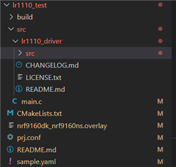
Any help would be really appreciated. Thanks in advance

--

Regards

Why do I need to configure this? For SPI or CS Signal? No sample code is doing that.
I am using P0.13 (SCK), P0.12 (MISO), P0.11(MOSI) & P0. 21(CS)
Sorry if it's too basic. 
Secondly, can I configure it using nrf9160dk_nrf9160ns.overlay?

Parents
  • Apologies, I marked my reply as an answer so couldn't open that again. Waiting for your answer.

  • What version the nRF9160 DK are you using? What version of nRF Connect SDK are you using?

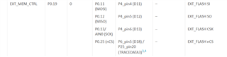
    From the nRF9160 DK board control chapter in the nRF9160 DK User Guide. 

  • Hi Øyvind,
    Thank you for the detailed reply.
    Just curious, do I need to change the board controller firmware in order to run SPI on any available PINs of NRF9160 -DK? Let's say if I change the pins as SCK (P0.30), MISO (P0.27), MOSI (P0.31) & CS (P0.12). 
    --

    Regards

  • Hi, 

    Sohaib Qamar said:
    do I need to change the board controller firmware in order to run SPI on any available PINs of NRF9160 -DK?

    No, if you change your pins to available pins on the DK, that are not connected through the board controller, you should be good. 

    Kind regards,
    Øyvind

  • Hi Øyvind,

    I have checked the schematics of my board 0.8.3 and flashed Hello Word with a changed overlay file in nRF52840. I can change the CS signal now manually, my SPI is working when I toggle the CS signal manually before executing


    nrfx_err_t ret = nrfx_spim_xfer(&spi, &xfer_desc, 0);

    Secondly, below statement Turn CS line LOW instead of HIGH

    gpio_pin_set(gpiodev, PIN, true);

    Looking for recommendations, how my SPI can work without manual control of CS line.

    --

    Regards
    Sohaib

  • Sohaib Qamar said:
    I can change the CS signal now manually, my SPI is working when I toggle the CS signal manually before executing

    Please note that SPIM peripheral of the nRF9160 does not implement support for chip select directly. Therefore, the CPU must use available GPIOs to select the correct slave and control this independently of the SPI master. The SPIM supports SPI modes 0 through 3. The CONFIG register allows setting CPOL and CPHA appropriately.

    Have a look at this thread on DevZone:
    https://devzone.nordicsemi.com/f/nordic-q-a/70105/how-to-use-spi-interface-in-a-zephyr-sample-example


  • Hi,

    Thanks for the guidance, I am able to send SPI commands successfully on my DK board with LR1110.

    Now I need a BUSY signal from LR1110 to be read before making any SPI transactions for continuous communication using the LR1110 library. Secondly, I need one other Pin as Output for making the LR1110 Reset. 

    My question is how can I use these two pins (One as Input and the other as Output) in lr1110_hal.c file.

    Do I need to define these Pins in .dts or .overlay file as well?

    I'm using the below code to initialize the Input pin, but the code gets stuck.

    // This is my lr1110_hal.c file
    
    #include <zephyr.h>
    #include <device.h>
    #include <logging/log.h>
    #include <nrfx_spim.h>
    #include <drivers/nrfx_errors.h>
    #include <drivers/gpio.h>
    #include "lr1110_hal.h"
    
    const struct device *dev_gpio;
    #define LR_BUSY_PIN 13
    
    void setup_spim(void)
    {
       	nrfx_spim_config_t spi_config = 	NRFX_SPIM_DEFAULT_CONFIG(
    		NRFX_SPIM_SCK_PIN, 
    		NRFX_SPIM_MOSI_PIN,
    		NRFX_SPIM_MISO_PIN,
    		NRFX_SPIM_SS_PIN);
       	printk("Setting SPI\n");
    	//uint32_t err = nrfx_spim_init(&spi, &spi_config, spim_event_handler, NULL);
    	uint32_t err = nrfx_spim_init(&spi, &spi_config, NULL, NULL);
    	if (err == NRFX_ERROR_INVALID_STATE) {
    		printk("nrfx INIT NRFX_ERROR_INVALID_STATE\n");
    		return;
    	}
    	if (err == NRFX_ERROR_BUSY) {
    		printk("nrfx INIT NRFX_ERROR_BUSY\n");
    		return;
    	}
    	if (err == NRFX_ERROR_NOT_SUPPORTED) {
    		printk("nrfx INIT NRFX_ERROR_NOT_SUPPORTED\n");
    		return;
    	}
    	if (err != NRFX_SUCCESS) {
    		printk("nrfx INIT err: %d\n", err);
    		return;
    	}
       	printk("SPI SET\n");
    	
    	int retErr;
    	retErr = gpio_pin_configure(dev_gpio, LR_BUSY_PIN, GPIO_INPUT);
    	if(retErr != 0) {
    		printk("GPIO config err.\n");
    		return;
    	}
    }
    
    void testInput()
    {
        int isPinActive = gpio_pin_get(dev_gpio, LR_BUSY_PIN);
        printk("Pin: %d - isActive: %d\n", LR_BUSY_PIN, isPinActive);
    }

    The above functions are being called by the main.c file.

    What else do I need to add for initializing the GPIO Input pin and what do I need to add further for Output Pin.

    Thanks in Advance

    --
    Regards
    Sohaib

Reply
  • Hi,

    Thanks for the guidance, I am able to send SPI commands successfully on my DK board with LR1110.

    Now I need a BUSY signal from LR1110 to be read before making any SPI transactions for continuous communication using the LR1110 library. Secondly, I need one other Pin as Output for making the LR1110 Reset. 

    My question is how can I use these two pins (One as Input and the other as Output) in lr1110_hal.c file.

    Do I need to define these Pins in .dts or .overlay file as well?

    I'm using the below code to initialize the Input pin, but the code gets stuck.

    // This is my lr1110_hal.c file
    
    #include <zephyr.h>
    #include <device.h>
    #include <logging/log.h>
    #include <nrfx_spim.h>
    #include <drivers/nrfx_errors.h>
    #include <drivers/gpio.h>
    #include "lr1110_hal.h"
    
    const struct device *dev_gpio;
    #define LR_BUSY_PIN 13
    
    void setup_spim(void)
    {
       	nrfx_spim_config_t spi_config = 	NRFX_SPIM_DEFAULT_CONFIG(
    		NRFX_SPIM_SCK_PIN, 
    		NRFX_SPIM_MOSI_PIN,
    		NRFX_SPIM_MISO_PIN,
    		NRFX_SPIM_SS_PIN);
       	printk("Setting SPI\n");
    	//uint32_t err = nrfx_spim_init(&spi, &spi_config, spim_event_handler, NULL);
    	uint32_t err = nrfx_spim_init(&spi, &spi_config, NULL, NULL);
    	if (err == NRFX_ERROR_INVALID_STATE) {
    		printk("nrfx INIT NRFX_ERROR_INVALID_STATE\n");
    		return;
    	}
    	if (err == NRFX_ERROR_BUSY) {
    		printk("nrfx INIT NRFX_ERROR_BUSY\n");
    		return;
    	}
    	if (err == NRFX_ERROR_NOT_SUPPORTED) {
    		printk("nrfx INIT NRFX_ERROR_NOT_SUPPORTED\n");
    		return;
    	}
    	if (err != NRFX_SUCCESS) {
    		printk("nrfx INIT err: %d\n", err);
    		return;
    	}
       	printk("SPI SET\n");
    	
    	int retErr;
    	retErr = gpio_pin_configure(dev_gpio, LR_BUSY_PIN, GPIO_INPUT);
    	if(retErr != 0) {
    		printk("GPIO config err.\n");
    		return;
    	}
    }
    
    void testInput()
    {
        int isPinActive = gpio_pin_get(dev_gpio, LR_BUSY_PIN);
        printk("Pin: %d - isActive: %d\n", LR_BUSY_PIN, isPinActive);
    }

    The above functions are being called by the main.c file.

    What else do I need to add for initializing the GPIO Input pin and what do I need to add further for Output Pin.

    Thanks in Advance

    --
    Regards
    Sohaib

Children
No Data
Related