Hello there,
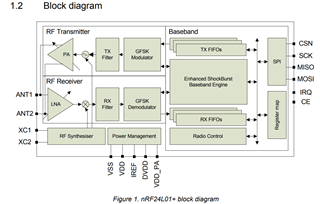
I'm trying to make a transceiver simulation on nRF24L01+ using Simulink. The block diagram provided in the documentation/datasheet was not clear enough for me. For example the Tx or Rx Filters after the GFSK Modulation block. what are they? How can I represent them in Simulink? Is there anyone that has presented a Simulink model of the nRF24L01+ model? The project is based on audio transmission between transceivers which are mainly used for Active Noise Control Application.