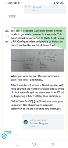
Continuous one sided drift in frequency measurement over GPIOTE.

Using above strategy for frequency measurement. Frequency source connected with one gpio pin.

Only GPIOTE PPI Timer modules are involved

HFXO is in use full time through sd_...request command

Frequency observed is showing a one sided trend, which continues for day. A fix source of frequency is connected to gpio, below shared graph shows frequency tick counted on nrf side via gpio.
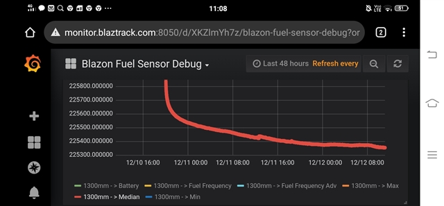
Same source of frequency, which is in production already, normally shows a minor drift which goes up and down w.r.t. day night temperature in a periodic manner.

Whole of implementation is following below reference

https://devzone.nordicsemi.com/f/nordic-q-a/9036/measuring-input-gpio-pin-frequency-with-soft-device-running

Unable to debug this behaviour, no interrupts are used, all the modules are interconnected via PPI module. All sources of drift , crystal, frequency generator should act according to ambient temperature. Which should be roughly periodic. Supply voltage is also plotted and their is no such one sided trend in that.


Parents
  • Hi,

    The way you describe it this looks like it is entirely HW related, as using only a TIMER running of the HFXO, GPIOTE and PPI would not involve any CPU activity, and so this should be deterministic with regards to clock cycles. It would be good to take a look at your test firmware though, just to be sure.

    Other than that, it would also be good to take a lock at your HW, particularly your crystal and load cap values, and also know more about the test conditions (temperature variations, for instance).

    Lastly, what external instruments do you use to measure the GPIO toggling frequency? Could it be that what you see is related to an issue with the measuring equipment/setup?

Reply
  • Hi,

    The way you describe it this looks like it is entirely HW related, as using only a TIMER running of the HFXO, GPIOTE and PPI would not involve any CPU activity, and so this should be deterministic with regards to clock cycles. It would be good to take a look at your test firmware though, just to be sure.

    Other than that, it would also be good to take a lock at your HW, particularly your crystal and load cap values, and also know more about the test conditions (temperature variations, for instance).

    Lastly, what external instruments do you use to measure the GPIO toggling frequency? Could it be that what you see is related to an issue with the measuring equipment/setup?

Children
  • Firmware is attached at the end.

    Regarding HW we are using a ready made ble module based on nrf58232.

    Testing is done in ambient environment.

    External frequency source is being measured in parallel via another frequency reader and am sharing a relative plot. Upper graph showing nrf reading, lower is showing a parallel reading with our existing in-production frequency reader.

    https://drive.google.com/file/d/1fKTHddlG9pApBo_hFRdMvGUL5wchaozM/view?usp=sharing

    ////////////////////////////////////////

    #include "gpiote_driver.h"
    
    #define FULE_FREQ_PIN 8
    
    #define TASK_TIMER_TIMER1_INTERVAL             1000  // Timer interval in milliseconds
    
    static nrf_drv_timer_t tasktimer = NRF_DRV_TIMER_INSTANCE(1);
    static nrf_drv_timer_t fftimer = NRF_DRV_TIMER_INSTANCE(2);
    
    uint32_t fuelFrequency = 0;
    
    void tasktimer_handler(nrf_timer_event_t event_type, void * p_context)
    {
        NRF_TIMER1->EVENTS_COMPARE[0] = 0;
        
        NRF_TIMER2->TASKS_CAPTURE[0] = 1;
    
        //if(nrf_timer_event_check(tasktimer.p_reg, NRF_TIMER_EVENT_COMPARE0)){
        
          fuelFrequency = (double)NRF_TIMER2->CC[0];
          insertToArr(fuelFrequency);
          NRF_LOG_INFO("Fuel Frequency : %ld", fuelFrequency);
          fuelFrequency = 0;
    
        //}    
        
    
        NRF_TIMER1->TASKS_CLEAR = 1;
    
        NRF_TIMER2->TASKS_CLEAR = 1;	
                                        
        NRF_TIMER2->TASKS_START = 1;		
    }
    
    void timer_dummy_handler(nrf_timer_event_t event_type, void * p_context){}
    
    void gpiote_event_handler(nrf_drv_gpiote_pin_t pin, nrf_gpiote_polarity_t action){}
    
    void gpiote_init(void)
    {
        ret_code_t err_code;
        uint32_t gpiote_evt_addr;
        uint32_t timer_task_addr;
        uint32_t timer_task_stop_addr;
        uint32_t timer_evt_addr;
        nrf_ppi_channel_t timer_ppi_channel;
        nrf_ppi_channel_t gpiote_ppi_channel;
    
        
        // Timer 1 Initilize
        nrf_drv_timer_config_t tasktimer_cfg = NRF_DRV_TIMER_DEFAULT_CONFIG;
        tasktimer_cfg.frequency = NRF_TIMER_FREQ_31250Hz;
        err_code = nrf_drv_timer_init(&tasktimer, &tasktimer_cfg, tasktimer_handler);
        APP_ERROR_CHECK(err_code);
        //nrf_timer_task_trigger(tasktimer.p_reg, NRF_TIMER_TASK_CLEAR);
        //nrf_timer_event_clear(tasktimer.p_reg, NRF_TIMER_EVENT_COMPARE0);
        //nrf_drv_timer_compare(&tasktimer, NRF_TIMER_CC_CHANNEL0, nrf_drv_timer_ms_to_ticks(&tasktimer, TASK_TIMER_TIMER1_INTERVAL), true);
        nrf_drv_timer_extended_compare(&tasktimer, NRF_TIMER_CC_CHANNEL0, nrf_drv_timer_ms_to_ticks(&tasktimer, TASK_TIMER_TIMER1_INTERVAL), NRF_TIMER_SHORT_COMPARE0_CLEAR_MASK, true);
        timer_evt_addr = nrf_drv_timer_event_address_get(&tasktimer, NRF_TIMER_EVENT_COMPARE0);
        
        NRF_LOG_INFO("TIMER 1 Initilized.");
        
    
        // Timer 2 Initilize
        nrf_drv_timer_config_t timer_cfg = NRF_DRV_TIMER_DEFAULT_CONFIG;
        timer_cfg.bit_width = NRF_TIMER_BIT_WIDTH_32;
        timer_cfg.mode = NRF_TIMER_MODE_COUNTER;
        err_code = nrf_drv_timer_init(&fftimer, &timer_cfg, timer_dummy_handler);
        APP_ERROR_CHECK(err_code);
        timer_task_addr = nrf_drv_timer_task_address_get(&fftimer, NRF_TIMER_TASK_COUNT);
        timer_task_stop_addr = nrf_drv_timer_task_address_get(&fftimer, NRF_TIMER_TASK_STOP);
    
        NRF_LOG_INFO("TIMER 2 Initilized.");
        
    
        // GPIOTE Initilize
        //Check if the GPIOTE is initialized
        if (nrf_drv_gpiote_is_init() == NULL) {
          //If its not initialized, init it now
          err_code = nrf_drv_gpiote_init(); //Init the GPIO interrupt and tasks
          APP_ERROR_CHECK(err_code); //Check the error code 
          //(0x8 means the GPIOTE module is already enabled)
        }
    
        nrf_drv_gpiote_in_config_t inConfig = GPIOTE_CONFIG_IN_SENSE_LOTOHI(true);
        err_code = nrf_drv_gpiote_in_init(FULE_FREQ_PIN, &inConfig, gpiote_event_handler);
        APP_ERROR_CHECK(err_code);
    
        nrf_drv_gpiote_in_event_enable(FULE_FREQ_PIN, false);
        gpiote_evt_addr = nrf_drv_gpiote_in_event_addr_get(FULE_FREQ_PIN);
    
        NRF_LOG_INFO("GPIOTE Initilized.");
    
    
        // GPIOTE PPI Initilize
        err_code = nrf_drv_ppi_init();
        APP_ERROR_CHECK(err_code);
    
        err_code = nrf_drv_ppi_channel_alloc(&gpiote_ppi_channel);
        APP_ERROR_CHECK(err_code);
    
        err_code = nrf_drv_ppi_channel_assign(gpiote_ppi_channel, gpiote_evt_addr, timer_task_addr);
        APP_ERROR_CHECK(err_code);
    
        // Enable the PPI channel.
        err_code = nrf_drv_ppi_channel_enable(gpiote_ppi_channel);
        APP_ERROR_CHECK(err_code);
    
        NRF_LOG_INFO("GPIOTE PPI Initilized.");
    
        
        // timer PPI Initilize
        //err_code = nrf_drv_ppi_init();
        //APP_ERROR_CHECK(err_code);
    
        err_code = nrf_drv_ppi_channel_alloc(&timer_ppi_channel);
        APP_ERROR_CHECK(err_code);
    
        err_code = nrf_drv_ppi_channel_assign(timer_ppi_channel, timer_evt_addr, timer_task_stop_addr);
        APP_ERROR_CHECK(err_code);
    
        // Enable the PPI channel.
        err_code = nrf_drv_ppi_channel_enable(timer_ppi_channel);
        APP_ERROR_CHECK(err_code);
    
        NRF_LOG_INFO("Timer PPI Initilized.");


        nrf_drv_timer_enable(&tasktimer);
        nrf_drv_timer_enable(&fftimer);
    
        NRF_LOG_INFO("GPIOTE Init Done.");
    }

  • Hi,

    Why do you use two timers here? And why do you clear the timers in the interrupt handler (I see you also clear timer 1 using a short). You should ensure that you have no SW involved in this after configuring the setup, simply use a single timer that toggles the GPIO via PPI, and is cleared using a short. That way, no SW is involved. This should be the first step.

  • Correct me if my understanding is incorrect. 

    I should use a single timer in counter mode. Gpiote is linked to increment it.

    Start it -> wait for fixed time -> capture the value -> clear it

    Keep repeating. 

    Do I need to pause resume all interrupts, maybe soft device, while running this one iteration.

  • Ah, sorry. I read your original post too fast and misread it, and then got confused because the code did not do what I expected it to do (which was to simply toggle a GPIO based on the TIMER via PPI).

    For measuring a frequency on a GPIO input this looks sensible.

    The problem here then is that the nRF is measuring the frequency of an external device, and you would expect that frequency to be stable. As there is a drift here, there is a relative change in frequency between the clock in the nRF and the clock in the device generating the signal. There is nothing in your measurements that indicate which of the devices has most of the clock drift though.

    If you have a proper high accuracy frequency counter instrument I suggest you use that to measure the frequency accuracy of both the nRF and the other device, which generates this signal. To measure it for the nRF you can use the GPIOTE Example (just modify it to use a higher frequency).

Related