

Hi,
I am using AFE4403 and Nrf52840, I want to assign a pin as output oscillator 4M using a nrf52 internal oscillator,
how to do that?
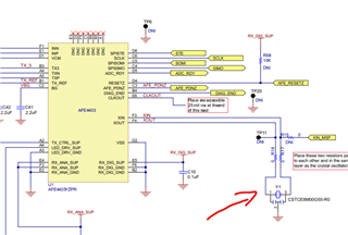
I am beginner , is my first time using this and also to trying communicate in English haha
Hi,
I am using AFE4403 and Nrf52840, I want to assign a pin as output oscillator 4M using a nrf52 internal oscillator,
how to do that?
I am beginner , is my first time using this and also to trying communicate in English haha
Hi,
You can make a GPIO output pin toggle with a frequency of 4 MHz, that is no problem. Note that you should enable the HFXO to get a decent accuracy (so using the 32 MHz crystal as reference, not the internal RC oscillator). This must be done using a TIMER and GPIOTE, connected by PPI. This way the CPU is only needed for configuration. After that, this runs entirely in HW.
What you need to do here is essentially demonstrated by the GPIOTE Example (if using the nRF5 SDK). In that case, you just need to do the following modifications which mainly changes the prescaler so that the timer runs at 16 MHz, and sets the capture compare register to 2. I also use a different output pin, and start the HFXO to get an accurate reference. See modifications from the SDK 17.1 example here:
diff --git a/examples/peripheral/gpiote/main.c b/examples/peripheral/gpiote/main.c
index 775cb0d..3654016 100644
--- a/examples/peripheral/gpiote/main.c
+++ b/examples/peripheral/gpiote/main.c
@@ -58,12 +58,9 @@
 #include "nrf_drv_gpiote.h"
 #include "app_error.h"

-#ifdef BSP_LED_0
-    #define GPIO_OUTPUT_PIN_NUMBER BSP_LED_0  /**< Pin number for output. */
-#endif
-#ifndef GPIO_OUTPUT_PIN_NUMBER
-    #error "Please indicate output pin"
-#endif
+
+#define GPIO_OUTPUT_PIN_NUMBER NRF_GPIO_PIN_MAP(1, 9)  /**< Output pin number (P1.09) */
+

 static nrf_drv_timer_t timer = NRF_DRV_TIMER_INSTANCE(0);

@@ -81,7 +78,7 @@ static void led_blinking_setup()
     APP_ERROR_CHECK(err_code);


-    nrf_drv_timer_extended_compare(&timer, (nrf_timer_cc_channel_t)0, 200 * 1000UL, NRF_TIMER_SHORT_COMPARE0_CLEAR_MASK, false);
+    nrf_drv_timer_extended_compare(&timer, (nrf_timer_cc_channel_t)0, 2, NRF_TIMER_SHORT_COMPARE0_CLEAR_MASK, false);

     err_code = nrf_drv_ppi_channel_alloc(&ppi_channel);
     APP_ERROR_CHECK(err_code);
@@ -98,6 +95,23 @@ static void led_blinking_setup()
     nrf_drv_gpiote_out_task_enable(GPIO_OUTPUT_PIN_NUMBER);
 }

+
+/** @brief Function for configuring all peripherals used in this example.
+ */
+static void hfxo_init(void)
+{
+    // Start 64 MHz crystal oscillator.
+    NRF_CLOCK->EVENTS_HFCLKSTARTED = 0;
+    NRF_CLOCK->TASKS_HFCLKSTART    = 1;
+
+    // Wait for the external oscillator to start up.
+    while (NRF_CLOCK->EVENTS_HFCLKSTARTED == 0)
+    {
+        // Do nothing.
+    }
+}
+
+
 /**
  * @brief Function for application main entry.
  */
@@ -105,6 +119,8 @@ int main(void)
 {
     ret_code_t err_code;

+    hfxo_init();
+
     err_code = nrf_drv_ppi_init();
     APP_ERROR_CHECK(err_code);

@@ -112,6 +128,7 @@ int main(void)
     APP_ERROR_CHECK(err_code);

     nrf_drv_timer_config_t timer_cfg = NRF_DRV_TIMER_DEFAULT_CONFIG;
+    timer_cfg.frequency = NRF_TIMER_FREQ_16MHz;
     err_code = nrf_drv_timer_init(&timer, &timer_cfg, timer_dummy_handler);
     APP_ERROR_CHECK(err_code);
 #ifdef NRF51
You can also use the same approach with the nRF Connect SDK.
Hi,
You can make a GPIO output pin toggle with a frequency of 4 MHz, that is no problem. Note that you should enable the HFXO to get a decent accuracy (so using the 32 MHz crystal as reference, not the internal RC oscillator). This must be done using a TIMER and GPIOTE, connected by PPI. This way the CPU is only needed for configuration. After that, this runs entirely in HW.
What you need to do here is essentially demonstrated by the GPIOTE Example (if using the nRF5 SDK). In that case, you just need to do the following modifications which mainly changes the prescaler so that the timer runs at 16 MHz, and sets the capture compare register to 2. I also use a different output pin, and start the HFXO to get an accurate reference. See modifications from the SDK 17.1 example here:
diff --git a/examples/peripheral/gpiote/main.c b/examples/peripheral/gpiote/main.c
index 775cb0d..3654016 100644
--- a/examples/peripheral/gpiote/main.c
+++ b/examples/peripheral/gpiote/main.c
@@ -58,12 +58,9 @@
 #include "nrf_drv_gpiote.h"
 #include "app_error.h"

-#ifdef BSP_LED_0
-    #define GPIO_OUTPUT_PIN_NUMBER BSP_LED_0  /**< Pin number for output. */
-#endif
-#ifndef GPIO_OUTPUT_PIN_NUMBER
-    #error "Please indicate output pin"
-#endif
+
+#define GPIO_OUTPUT_PIN_NUMBER NRF_GPIO_PIN_MAP(1, 9)  /**< Output pin number (P1.09) */
+

 static nrf_drv_timer_t timer = NRF_DRV_TIMER_INSTANCE(0);

@@ -81,7 +78,7 @@ static void led_blinking_setup()
     APP_ERROR_CHECK(err_code);


-    nrf_drv_timer_extended_compare(&timer, (nrf_timer_cc_channel_t)0, 200 * 1000UL, NRF_TIMER_SHORT_COMPARE0_CLEAR_MASK, false);
+    nrf_drv_timer_extended_compare(&timer, (nrf_timer_cc_channel_t)0, 2, NRF_TIMER_SHORT_COMPARE0_CLEAR_MASK, false);

     err_code = nrf_drv_ppi_channel_alloc(&ppi_channel);
     APP_ERROR_CHECK(err_code);
@@ -98,6 +95,23 @@ static void led_blinking_setup()
     nrf_drv_gpiote_out_task_enable(GPIO_OUTPUT_PIN_NUMBER);
 }

+
+/** @brief Function for configuring all peripherals used in this example.
+ */
+static void hfxo_init(void)
+{
+    // Start 64 MHz crystal oscillator.
+    NRF_CLOCK->EVENTS_HFCLKSTARTED = 0;
+    NRF_CLOCK->TASKS_HFCLKSTART    = 1;
+
+    // Wait for the external oscillator to start up.
+    while (NRF_CLOCK->EVENTS_HFCLKSTARTED == 0)
+    {
+        // Do nothing.
+    }
+}
+
+
 /**
  * @brief Function for application main entry.
  */
@@ -105,6 +119,8 @@ int main(void)
 {
     ret_code_t err_code;

+    hfxo_init();
+
     err_code = nrf_drv_ppi_init();
     APP_ERROR_CHECK(err_code);

@@ -112,6 +128,7 @@ int main(void)
     APP_ERROR_CHECK(err_code);

     nrf_drv_timer_config_t timer_cfg = NRF_DRV_TIMER_DEFAULT_CONFIG;
+    timer_cfg.frequency = NRF_TIMER_FREQ_16MHz;
     err_code = nrf_drv_timer_init(&timer, &timer_cfg, timer_dummy_handler);
     APP_ERROR_CHECK(err_code);
 #ifdef NRF51
You can also use the same approach with the nRF Connect SDK.
