nRF52805 antenna matching

I need your help to design the radio matching network on device nRF52805.

Here the reference design:
infocenter.nordicsemi.com/index.jsp
In this reference design L1, L2 and C3 are used to match the output impedance of the ANT pin #E1 that it is not 50 Ohm.

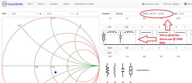
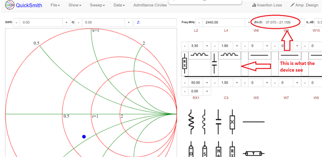
Can you please let me know what is the impedance that the device wants to see on ANT pin #E1 (from device to output) ? I read some where that it is 37 - j20 ohm

Thank you

Parents
  • It's not a good idea to match the radio to the antenna directly. You will most probably not have enough attenuation of the harmonics there are serious risks of failing radio qualification testing. 

    The reference design takes care of both the impedance transformation and low pass filtering. You can measure S22 when the radio is in TX mode. It's expected to see ~50 ohm into the matching network from the antenna side. 

    The radio is expecting to see 37 - j20 ohm

Reply
  • It's not a good idea to match the radio to the antenna directly. You will most probably not have enough attenuation of the harmonics there are serious risks of failing radio qualification testing. 

    The reference design takes care of both the impedance transformation and low pass filtering. You can measure S22 when the radio is in TX mode. It's expected to see ~50 ohm into the matching network from the antenna side. 

    The radio is expecting to see 37 - j20 ohm

Children
Related