This discussion has been locked.
You can no longer post new replies to this discussion. If you have a question you can start a new discussion

Open Bootloader Stuck in DFU Mode (Nano 33 BLE Issue. DK Is OK)

Good evening,

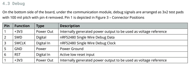
I’m testing the SDK v17.1.0 “Open Bootloader with DFU” example. I’m using Segger Embedded Studio to program my Nano 33 BLE via the debug interface (P20) of my nRF52840-DK. I’m also programming the Open Bootloader to my DK via its “USB IF MCU” (J2).

nRF52840-DK (As expected)

Everything works as expected… I erase the chip and then program the DK with the Open Bootloader example via the DK’s MCU USB (J2). My Windows PC’s Device Manager lists both the “JLink CDC UART” and the “nRF52 SDFU USB” under Ports. I then use nRF Util to program “blinky” to the DK via its “nRF USB (J3)”.

Blinky now makes the 4 LEDs blink, and SDFU USB disappears from device manager as expected. If I then press the “IF BOOT/RESET” button, the DK goes into DFU mode; its SDFU USB reappears in device manager. No amount of waiting reactivates blinky. Next, I turn the DK off and on via its “SW8 Power” switch. Blinky is then running again.

Nano 33 BLE (Only works at first)

The programming procedure is of course the same as for the DK, i.e., erase the chip, program the bootloader to it, and then use nRF Util to program it with blinky.

Pressing the nano’s button causes it to exit (yellow LED off; SDFU USB disappears from device manager) DFU mode. Releasing the nano’s button causes it to enter DFU mode. This seems to be the reverse of what I was expecting.

Immediately after programming blinky to the nano, blinky runs, but after pressing and releasing the nano’s button or powering it off and on, the nano is then stuck in DFU mode. The only way to get blinky working again is to program it again using nRF Util. Incidentally, DFU mode always works via the nano’s button as described above. The nano's bootloader is only ever erased if I erase the nano's chip via the DK’s debug interface.

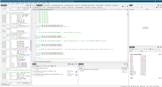
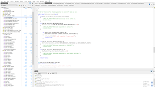
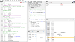
After reading “How does the bootloader load the application…”, I decided to trace “nrf_bootloader_app_start()”. It is defined in “nrf_bootloader_app_start.c”, and called from “nrf_bootloader_init(nrf_dfu_observer_t observer)” which itself is defined in “nrf_bootloader.c”.

By commenting nrf_bootloader_app_start(), blinky then never runs which is no surprise, and the bootloader remains functional which is also no surprise.

Please can somebody help me understand how to proceed from here to get the bootloader working as desired for the nano? I’m hoping it’ll perhaps be relatively straightforward, e.g., change certain settings within “sdk_config.h”?

Thank you, Gary.

Parents
  • Hi Gary, 

    There is a function called dfu_enter_check(). It's where the bootloader check if it should stay in DFU mode or jump to the application. 

    Could you check if any condition inside the function actually make the function returns true ? 

    I suspect that NRF_BL_DFU_ENTER_METHOD_BUTTON was set to 1 and the NRF_BL_DFU_ENTER_METHOD_BUTTON_PIN was not configured (or mounted) to correct level (active low I believe) causing the device entering bootloader mode. It's equivalent to the normal way of entering (secure )DFU of holding Button 1 when resetting the device. 

  • I can see: dfu_enter_check() within: nrf_bootloader.c. Via "Step Into" I can see which file is being executed because they're all open at the top of the main window and become highlighted one by one, and that function isn't reached, i.e., it just gets stuck in the CRC check.

    Do you know why it continues on successfully... running blinky after clicking the green arrow (continue execution)? I.e., how does continue execution get it past the crc32_compute(...) function?

    Within sdk_config.h: NRF_BL_DFU_ENTER_METHOD_BUTTON is set to 0 by default.

    For: NRF_BL_DFU_ENTER_METHOD_BUTTON_PIN I've changed the default 25 to 999 (Edit: 0 also makes no difference) in an attempt to disable its effect, but it made no difference. So to experiment further I then changed NRF_BL_DFU_ENTER_METHOD_PINRESET from 1 to 0, but that also still didn't make any difference, i.e., the Nano's yellow light is still on by default (without pressing its button) and nRF52 SDFU USB is listed under Ports in Device Manage. Please see SES screenshot below... (Edit: setting ...PINRESET to 0 does actually disable DFU mode... see my next post for clarification)

  • Hi again Gary, 

    You can simply test by removing the function and make it always return false to test. I guess there must be other reason why it enter DFU.

    If you can use the log or a GPIO pin you can find which cause dfu_enter to return true. 

  • I've deleted my previous reply that was in this position, because it turns out that it was completely wrong...

    Bizarrely, my two Micro-USB leads (probably PC related) that I've been using, each behave differently. They've both been working for programming purposes between themselves and the PC, but one of them doesn't (at least not consistently) enumerate as a COM Port in Device Manager, i.e., I've now swapped the leads over and I'm getting consistent behaviour for my Nano.

    Edit: another thing was that Device Manager wasn't always refreshing after unplugging the nano, i.e., I had to hold its button pressed whilst unplugging it, or else it stayed listed under Ports. Anyway I've got the hang of all that now.

    100% it's NRF_BL_DFU_ENTER_METHOD_PINRESET that is triggering DFU mode. It's set to 1 by default in sdk_config.h, and if I change that to 0, or instead comment the if-statement within dfu_enter_check() (see screenshot), then it never enters DFU mode. This is absolutely consistent now.

    Therefore ...PINRESET is being activated by releasing the Nano's button. However, after having loaded blinky via nRF Util, and holding down the Nano's button whilst plugging it in, blinky still doesn't run. I wonder why?

    I suppose the first thing to do is reverse the Low / High state of the button. Do you know if there's a setting for this?

    Edit 2: also, please if possible can you explain how/where the nano's button press (or any other device's button press) is detected? And how it becomes associated with ...PINRESET?

    Edit 3: according to the nano’s datasheet, reset is pin 6 (but I'm wondering if this is referring to (i.e., also connected to) its button PB1... maybe not?)

Reply
  • I've deleted my previous reply that was in this position, because it turns out that it was completely wrong...

    Bizarrely, my two Micro-USB leads (probably PC related) that I've been using, each behave differently. They've both been working for programming purposes between themselves and the PC, but one of them doesn't (at least not consistently) enumerate as a COM Port in Device Manager, i.e., I've now swapped the leads over and I'm getting consistent behaviour for my Nano.

    Edit: another thing was that Device Manager wasn't always refreshing after unplugging the nano, i.e., I had to hold its button pressed whilst unplugging it, or else it stayed listed under Ports. Anyway I've got the hang of all that now.

    100% it's NRF_BL_DFU_ENTER_METHOD_PINRESET that is triggering DFU mode. It's set to 1 by default in sdk_config.h, and if I change that to 0, or instead comment the if-statement within dfu_enter_check() (see screenshot), then it never enters DFU mode. This is absolutely consistent now.

    Therefore ...PINRESET is being activated by releasing the Nano's button. However, after having loaded blinky via nRF Util, and holding down the Nano's button whilst plugging it in, blinky still doesn't run. I wonder why?

    I suppose the first thing to do is reverse the Low / High state of the button. Do you know if there's a setting for this?

    Edit 2: also, please if possible can you explain how/where the nano's button press (or any other device's button press) is detected? And how it becomes associated with ...PINRESET?

    Edit 3: according to the nano’s datasheet, reset is pin 6 (but I'm wondering if this is referring to (i.e., also connected to) its button PB1... maybe not?)

Children
  • Hi Gary, 

    The reset pin of nRF52840 is pin P0.18. Please double check on the schematic of the Nano board (and the ublox module) to see how P0.18 is connected. 

    You can disable pin reset if you want (change PSELRESET register).

    In many applications, you don't want to enter DFU mode every time you do a pin reset, but instead having an extra button to switch it to DFU mode. If it's the case you need to modify the NRF_BL_DFU_ENTER_METHOD_PINRESET  to 0 and NRF_BL_DFU_ENTER_METHOD_BUTTON_PIN  to 1. 

    Another test you can do is to flash a normal application (not the bootloader) and do a power reset on the Nano, and check the value of NRF_POWER-> RESETREAS register to double check if reset pin is always triggered on power reset.

  • Thanks Hung,

    Did you mean to say NRF_BL_DFU_ENTER_METHOD_BUTTON to 1 (0 is the default)? If not then...

    For NRF_BL_DFU_ENTER_METHOD_BUTTON_PIN (25 is the default). Therefore why set it to 1?

    You can disable pin reset if you want (change PSELRESET register).

    Is that necessary considering that NRF_BL_DFU_ENTER_METHOD_PINRESET 0 disables activating DFU mode by ignoring the pin reset event? (Or do you mean that if I ever want to disable pin reset in general, then I can use its register?)

    In many applications, you don't want to enter DFU mode every time you do a pin reset, but instead having an extra button to switch it to DFU mode.

    Ah, so the Nano's reset button is essentially for resetting all pins, which is done by it being connected to P0.18. So you're simply saying to disable pin reset by setting _METHOD_PINRESET to 0 (or disable the pin reset event directly via its register, as mentioned above), and therefore the Nano's PB1 button can be used to activate DFU mode via _METHOD_BUTTON instead, and therefore as a point of interest, I suppose the button press itself must be registered independent of the pin reset event...  

    I've checked, and the Nano's button PB1 is indeed connected to P0.18, and so I've tried with _METHOD_BUTTON 1 and _METHOD_BUTTON_PIN 18 (_METHOD_PINRESET 0). The result is...

    1. Me remembering to uncomment previous changes to avoid being called a "Wally" Grinning
    2. Bootloader detects no valid application and therefore enters DFU mode = correct.
    3. Flash board with blinky via nRF Util and blinky runs = correct.
    4. Press PB1 which stops blinky running (i.e., all LEDs off) = correct, but it doesn't enter DFU mode = wrong. Also, blinky resumes running after releasing the button.

    I'll keep trying, but please if possible kindly respond to my previous questions, and let me know your further thoughts.

    The schematic is below (1st zoomed, 2nd full view)


    Edit_METHOD_BUTTON 1 & _METHOD_BUTTON_PIN to either 14 or 15 seems to work perfectly as below (also METHOD_PINRESET 0 of course)

    1. Bootloader detects no valid application and therefore enters DFU mode = correct.
    2. Flash board with blinky via nRF Util and blinky runs = correct.
    3. Press PB1 (sometimes requiring to keep it pressed for about 0.5 to 1 second) stops blinky running and then enters DFU mode when PB1 is released = seems to be correct.
    4. Press PB1 again and blinky resumes running = correct.

    However, how does it make any sense that it works for pins 14 and 15 and not others, including 18? (it was by pure chance that I changed the pin to 15, and so I then tested a few other values in my disbelief).

    Edit 2: this would be a celebration if I understood what was happening Interrobang Relaxed  

    Edit 3: so P0.14 (SDA1) and P0.15 (SCL1) are the I2C bus as stated for U-Blox NINA-B3X in the above schematic, and interrupting either of those two pins (which must be caused by pressing PB1), more or less consistently toggles between DFU mode and running blinky. Maybe this is just a lucky fluke? ... Incidentally, _METHOD_BUTTON_PIN 25 (the default) is button 4 on my nRF52840-DK Ok hand (I should have spotted that before).

    Edit 4: how is the SDK registering/configuring the Nano's button press, considering that it doesn't work for _METHOD_BUTTON_PIN 18 as explained above? (virtually the same question as "Edit 2" in my last reply).

    I'll wait for your reply, and thank you kindly Hung for your support so far. Cheers!

  • Is the correct solution to setup a GPIOTE for the Nano's PB1 button in my application via P0.18? Or is PB1 already configured as input? in which case this relates back to my Edit 4. Maybe similar to your reply in the thread as quoted below...

    ...Buttons don't work with a bootloader

    The bootloader I provided doesn't use GPIOTE Port event. It configures one button as input. As suggested by RK, have you made sure you reconfigured the button correctly in your application ?
  • Hi Gary, 
    Sorry it was my mistake, my intention was to set NRF_BL_DFU_ENTER_METHOD_BUTTON =1 not NRF_BL_DFU_ENTER_METHOD_BUTTON_PIN = 1.

    After you set NRF_BL_DFU_ENTER_METHOD_BUTTON =1 you then choose a PIN to be used as the reset to DFU pin. Let's say pin P0.05. Then to switch to DFU mode you need to hold the button that connect to P0.05 and do a reset, either a softreset, pin reset or a power reset. 
    When the bootloader booting up it will read the value of P0.05 and decide to enter DFU mode or not. It's not a GPIOTE event, but simply a pin read before entering DFU. 

    If you don't have an extra button to use and only have one single button PB1 that connect to P0.18 then you need to disable P0.18 as a reset pin ( via PSELRESET register) and set NRF_BL_DFU_ENTER_METHOD_BUTTON_PIN  to P0.18

  • Hi Hung,

    I meant happening regarding why 14 and 15 are doing what 18 should be doing Grinning but please notice my Edit 3 which attempted to explain (although I didn't know about soft reset and power reset, thanks, and for anyone curious... Reset Behaviour

    Anyway to now continue on from here by disabling PSELRESET as you've suggested... I've disabled both [0] and [1] because I don't know which one is relevant. I searched the entire solution for PSELRESET to avoid it being set after wherever I disable it, but it isn't found, so I decided to add them in main() as below...

    int main(void)
    {    
    	NRF_UICR->PSELRESET[0] = UICR_PSELRESET_CONNECT_Disconnected << UICR_PSELRESET_CONNECT_Pos;
    	NRF_UICR->PSELRESET[1] = UICR_PSELRESET_CONNECT_Disconnected << UICR_PSELRESET_CONNECT_Pos;
    	
    	uint32_t ret_val;
    	
    	// Must happen before flash protection is applied, since it edits a protected page.
    	nrf_bootloader_mbr_addrs_populate();
    	
    	// Protect MBR and bootloader code from being overwritten.
    	ret_val = nrf_bootloader_flash_protect(0, MBR_SIZE);
    	APP_ERROR_CHECK(ret_val);
    	ret_val = nrf_bootloader_flash_protect(BOOTLOADER_START_ADDR, BOOTLOADER_SIZE);
    	APP_ERROR_CHECK(ret_val);
    	
    	ret_val = NRF_LOG_INIT(app_timer_cnt_get);
    	APP_ERROR_CHECK(ret_val);
    	NRF_LOG_DEFAULT_BACKENDS_INIT();
    	
    	NRF_LOG_INFO("Open USB bootloader started");
    	NRF_LOG_FLUSH();
    	
    	ret_val = nrf_bootloader_init(dfu_observer);
    	APP_ERROR_CHECK(ret_val);
    	
    	NRF_LOG_FLUSH();
    	
    	NRF_LOG_ERROR("After main, should never be reached.");
    	NRF_LOG_FLUSH();
    	
    	APP_ERROR_CHECK_BOOL(false);
    }

    The result is exactly as before when not using pins 14 or 15... as the workaround that I discovered.

    Therefore, might PSELRESET be set after main() via some other method?

    Please confirm if I'm disabling this register correctly?

    Edit: just to confirm (although probably not surprising considering all that has tested to work so far), I am indeed using the _mbr version as below...

    1. nrfutil pkg generate --application blinky_pca10056_mbr.hex --application-version 1 --hw-version 52 --sd-req 0x00 app_dfu_package.zip
    2. nrfutil dfu usb-serial -pkg app_dfu_package.zip -p COM13 -b 115200

    Edit 2: I've discovered how to see the registers in SES Thinking here's a screenshot whilst in debug mode. You can see that both PSELRESET [0] and [1] state "Disconnected" (by default that is, i.e., my attempt to disable them in main() is commented). I'll wait for your reply, thank you...

    And for the PIN field I can only see one possible value... 18 (Please see screenshot below) so I'm guessing that doesn't apply, or does it?

    Edit (03-01-2022): the screenshot below is now for the correct chip (nRF52840), otherwise I would have asked about PORT as well Neutral face

Related