Maximum count speed of timer

I am trying to measure the frequency of the square wave on the ARDUINO_6_PIN on the NRF52840 Dev Kit. 


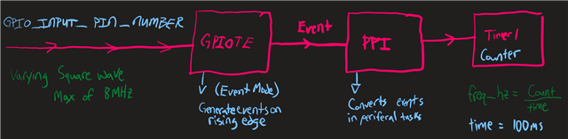
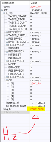
It seems like it works well until the square wave goes above 2MHz. Is this the maximum speed that this method can achieve or is there something else I need to do, (or another method I could use)?


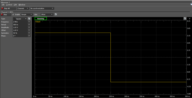
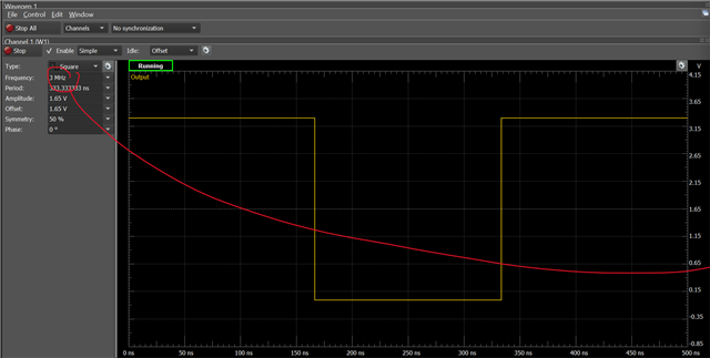
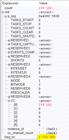
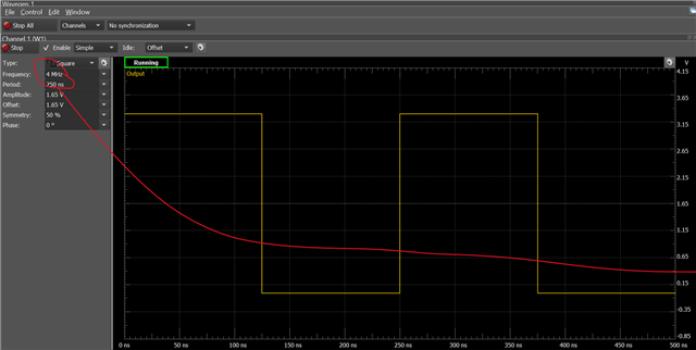
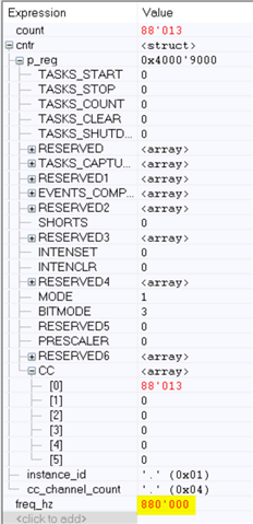
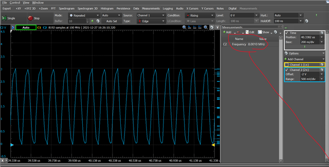
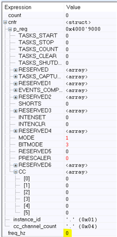
(My function generator cannot go above 6MHz itself so I generated the square wave on ARDUINO_7_PIN on the NRF52840)

To create this program I started with gpiote peripheral example in the nRF5_SDK_17.1.0_ddde560 and edited the sdk_config.h and the main.c linked here.  (Down below because I am an idiot)


  • Hi Donovan, 

    I assume the code you provided is only the code to generate the square wave ? 
    Could you also provide the code where you capture the square wave and measure using a counter ? 

    We have a similar question long ago and one of our engineer calculated the theoretically maximum capture speed of the GPIOTE here

  • Oops I linked the wrong files, I think those are the original example files.
    27413.sdk_config.h 

    /**
     * Copyright (c) 2014 - 2021, Nordic Semiconductor ASA
     *
     * All rights reserved.
     *
     * Redistribution and use in source and binary forms, with or without modification,
     * are permitted provided that the following conditions are met:
     *
     * 1. Redistributions of source code must retain the above copyright notice, this
     *    list of conditions and the following disclaimer.
     *
     * 2. Redistributions in binary form, except as embedded into a Nordic
     *    Semiconductor ASA integrated circuit in a product or a software update for
     *    such product, must reproduce the above copyright notice, this list of
     *    conditions and the following disclaimer in the documentation and/or other
     *    materials provided with the distribution.
     *
     * 3. Neither the name of Nordic Semiconductor ASA nor the names of its
     *    contributors may be used to endorse or promote products derived from this
     *    software without specific prior written permission.
     *
     * 4. This software, with or without modification, must only be used with a
     *    Nordic Semiconductor ASA integrated circuit.
     *
     * 5. Any software provided in binary form under this license must not be reverse
     *    engineered, decompiled, modified and/or disassembled.
     *
     * THIS SOFTWARE IS PROVIDED BY NORDIC SEMICONDUCTOR ASA "AS IS" AND ANY EXPRESS
     * OR IMPLIED WARRANTIES, INCLUDING, BUT NOT LIMITED TO, THE IMPLIED WARRANTIES
     * OF MERCHANTABILITY, NONINFRINGEMENT, AND FITNESS FOR A PARTICULAR PURPOSE ARE
     * DISCLAIMED. IN NO EVENT SHALL NORDIC SEMICONDUCTOR ASA OR CONTRIBUTORS BE
     * LIABLE FOR ANY DIRECT, INDIRECT, INCIDENTAL, SPECIAL, EXEMPLARY, OR
     * CONSEQUENTIAL DAMAGES (INCLUDING, BUT NOT LIMITED TO, PROCUREMENT OF SUBSTITUTE
     * GOODS OR SERVICES; LOSS OF USE, DATA, OR PROFITS; OR BUSINESS INTERRUPTION)
     * HOWEVER CAUSED AND ON ANY THEORY OF LIABILITY, WHETHER IN CONTRACT, STRICT
     * LIABILITY, OR TORT (INCLUDING NEGLIGENCE OR OTHERWISE) ARISING IN ANY WAY OUT
     * OF THE USE OF THIS SOFTWARE, EVEN IF ADVISED OF THE POSSIBILITY OF SUCH DAMAGE.
     *
     */
    /** @file
    *
    * @defgroup gpiote_example_main main.c
    * @{
    * @ingroup nrf_gpiote_example
    * @brief GPIOTE Example Application main file.
    *
    * This file contains the source code for a sample application using GPIOTE.
    */
    
    #include <stdbool.h>
    #include <stdint.h>
    #include "nrf.h"
    #include "nrf_gpiote.h"
    #include "nrf_gpio.h"
    #include "boards.h"
    #include "nrf_drv_ppi.h"
    #include "nrf_drv_timer.h"
    #include "nrf_drv_gpiote.h"
    #include "app_error.h"
    #include "nrfx_glue.h"
    #include "nrf_log.h"
    
    #define GPIO_OUTPUT_PIN_NUMBER ARDUINO_7_PIN
    #define GPIO_INPUT_PIN_NUMBER ARDUINO_6_PIN
    
    #define EIGHT_MHZ 1
    #define FOUR_KHZ 2000
    #define MS_DELAY 100
    
    static nrf_drv_timer_t timer = NRF_DRV_TIMER_INSTANCE(0);
    static nrf_drv_timer_t cntr = NRF_DRV_TIMER_INSTANCE(1);
    
    uint32_t count = 0;
    uint32_t freq_hz = 0;
    
    nrf_ppi_channel_t ppi_channel1;
    nrf_ppi_channel_t ppi_channel2;
    
    void timer_dummy_handler(nrf_timer_event_t event_type, void * p_context){}
    void cntr_dummy_handler(nrf_timer_event_t event_type, void * p_context){}
    void cntr_gpio_dummy_handler(nrfx_gpiote_pin_t pin, nrf_gpiote_polarity_t action){}
    
    static void led_blinking_setup()
    {
        uint32_t compare_evt_addr;
        uint32_t gpiote_task_addr;
        ret_code_t err_code;
        nrf_drv_gpiote_out_config_t config = GPIOTE_CONFIG_OUT_TASK_TOGGLE(false);
    
        err_code = nrf_drv_gpiote_out_init(GPIO_OUTPUT_PIN_NUMBER, &config);
        APP_ERROR_CHECK(err_code);
    
        nrf_drv_timer_extended_compare(&timer, (nrf_timer_cc_channel_t)0, EIGHT_MHZ, NRF_TIMER_SHORT_COMPARE0_CLEAR_MASK, false);
    
        compare_evt_addr = nrf_drv_timer_event_address_get(&timer, NRF_TIMER_EVENT_COMPARE0);
        gpiote_task_addr = nrf_drv_gpiote_out_task_addr_get(GPIO_OUTPUT_PIN_NUMBER);
    
        err_code = nrf_drv_ppi_channel_assign(ppi_channel1, compare_evt_addr, gpiote_task_addr);
        APP_ERROR_CHECK(err_code);
    
        err_code = nrf_drv_ppi_channel_enable(ppi_channel1);
        APP_ERROR_CHECK(err_code);
    
        nrf_drv_gpiote_out_task_enable(GPIO_OUTPUT_PIN_NUMBER);
    }
    
    static void cntr_setup()
    {
        uint32_t compare_task_addr;
        uint32_t gpiote_event_addr;
        ret_code_t err_code;
        nrf_drv_gpiote_in_config_t config =
        {
            .sense = NRF_GPIOTE_POLARITY_HITOLO,
            .pull = NRF_GPIO_PIN_NOPULL,
            .is_watcher = false,
            .hi_accuracy = true,
            .skip_gpio_setup = false
        };
    
        err_code = nrf_drv_gpiote_in_init(GPIO_INPUT_PIN_NUMBER, &config, cntr_gpio_dummy_handler);
        APP_ERROR_CHECK(err_code);
      
        nrf_drv_gpiote_in_event_enable(GPIO_INPUT_PIN_NUMBER, false);
    
        gpiote_event_addr = nrf_drv_gpiote_in_event_addr_get(GPIO_INPUT_PIN_NUMBER);
        compare_task_addr = nrf_drv_timer_task_address_get(&cntr, NRF_TIMER_TASK_COUNT);
    
        err_code = nrf_drv_ppi_channel_assign(ppi_channel2, gpiote_event_addr, compare_task_addr);
        APP_ERROR_CHECK(err_code);
    
        err_code = nrf_drv_ppi_channel_enable(ppi_channel2);
        APP_ERROR_CHECK(err_code);
    }
    
    /**
     * @brief Function for application main entry.
     */
    int main(void)
    {
        ret_code_t err_code;
    
        err_code = nrf_drv_ppi_init();
        APP_ERROR_CHECK(err_code);
        
        err_code = nrf_drv_ppi_channel_alloc(&ppi_channel1);
        APP_ERROR_CHECK(err_code);
        err_code = nrf_drv_ppi_channel_alloc(&ppi_channel2);
        APP_ERROR_CHECK(err_code);
    
        err_code = nrf_drv_gpiote_init();
        APP_ERROR_CHECK(err_code);
    
        nrf_drv_timer_config_t timer_cfg = 
        {
            .frequency          = (nrf_timer_frequency_t)NRF_TIMER_FREQ_16MHz,
            .mode               = (nrf_timer_mode_t)NRF_TIMER_MODE_TIMER,
            .bit_width          = (nrf_timer_bit_width_t)NRF_TIMER_BIT_WIDTH_32,
            .interrupt_priority = NRFX_TIMER_DEFAULT_CONFIG_IRQ_PRIORITY,
            .p_context          = NULL
        };
    
        nrf_drv_timer_config_t cntr_cfg = 
        {
            .frequency          = (nrf_timer_frequency_t)NRF_TIMER_FREQ_16MHz,
            .mode               = (nrf_timer_mode_t)NRF_TIMER_MODE_COUNTER,
            .bit_width          = (nrf_timer_bit_width_t)NRF_TIMER_BIT_WIDTH_32,
            .interrupt_priority = NRFX_TIMER_DEFAULT_CONFIG_IRQ_PRIORITY,
            .p_context          = NULL
        };
    
        err_code = nrf_drv_timer_init(&timer, &timer_cfg, timer_dummy_handler);
        err_code = nrf_drv_timer_init(&cntr, &cntr_cfg, cntr_dummy_handler);
        APP_ERROR_CHECK(err_code);
    
        led_blinking_setup();
    
        cntr_setup();
    
        nrf_drv_timer_enable(&timer);
        nrf_drv_timer_enable(&cntr);
    
        while (true)
        {
            count = 0;
            nrf_drv_timer_clear(&cntr);
            nrfx_coredep_delay_us(MS_DELAY*1000);
            count = nrfx_timer_capture( &cntr, NRF_TIMER_CC_CHANNEL0 );
            freq_hz = (count / (uint32_t)MS_DELAY) * 1000UL;
            NRF_LOG_INFO("%d", freq_hz);
            nrfx_coredep_delay_us(500000);
        }
    }


    That should be the updated ones, but your reply seems to agree with my findings. “If you have e.g. a 50% duty-cycle then max frequency will be 16 MHz / (3 low periods + 3 high periods) = 2.67 MHz.” Thanks for the response, I think I will have to figure out a different way to measure that signal.

Related