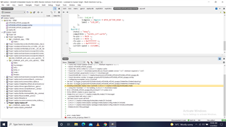
I added the uart overlay as shown in attached file. When, Run CMake is executed, the error is shown as in attached image.
I added the uart overlay as shown in attached file. When, Run CMake is executed, the error is shown as in attached image.

Dear Amanda, I am doing all work in SES and yet have free version of it. SO, please guide accordingly. Most of tutorials are from commnd line pont of view.

Hi,
It's related to how you set the overlay instead of IDE, and I have explained and provided the example in the previous reply. I would suggest you study Devicetree HOWTOs.
-Amanda
Hi, I tried to change the baud rate using overlay file as shown in attache files, but the ovrlay baud does not appear in zupher.dts 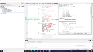 bms_nrf5340_cpuapp.overlay5545.zephyr.dts
Hi,
The modified overlay 3554.nrf5340dk_nrf5340_cpuapp.overlay look like this:
//****** lcd16x2 Overlay File ****
/{
  aliases{
        lcd0 = &lcd0;
        lcd1 = &lcd1;
        lcd2 = &lcd2;
        lcd3 = &lcd3;
        lcden = &lcden;
        lcdrs = &lcdrs;
        bmsserial = &uart0;
    };

    lcd16x2 {
        compatible = "lcd16x2-pins";
        status = "okay";
        lcd0: lcd_0 {
            lcdgpios = <&gpio1 10 GPIO_ACTIVE_HIGH >;
            label = "LCD_D0";
            status = "okay";
        };
        lcd1: lcd_1 {
            lcdgpios = <&gpio1 11 GPIO_ACTIVE_HIGH >;
            label = "LCD_D1";
            status = "okay";
        };
        lcd2: lcd_2 {
            lcdgpios = <&gpio1 12 GPIO_ACTIVE_HIGH >;
            label = "LCD_D2";
            status = "okay";
        };
        lcd3: lcd_3 {
            lcdgpios = <&gpio1 13 GPIO_ACTIVE_HIGH >;
            label = "LCD_D3";
            status = "okay";
        };
        lcdrs: lcd_rs {
            lcdgpios = <&gpio1 14 GPIO_ACTIVE_HIGH >;
            label = "LCD_RS";
            status = "okay";
        };
        lcden: lcd_en {
            lcdgpios = <&gpio1 15 GPIO_ACTIVE_HIGH >;
            label = "LCD_EN";
            status = "okay";
        };
    };

/*
    lcd16x2 {
        compatible = "lcd_pins";

        lcd0: lcd_0 {
            lcdgpios = <&arduino_header 10 GPIO_ACTIVE_HIGH>;
            label = "LCD_D0";
        };
        lcd1: lcd_1 {
            lcdgpios= <&arduino_header 11 GPIO_ACTIVE_HIGH>;
            label = "LCD_D1";
        };
        lcd2: lcd_2 {
            lcdgpios = <&arduino_header 12 GPIO_ACTIVE_HIGH>;
            label = "LCD_D2";
        };
        lcd3: lcd_3 {
            lcdgpios = <&arduino_header 13 GPIO_ACTIVE_HIGH>;
            label = "LCD_D3";
        };
        lcdrs: lcd_rs {
            lcdgpios = <&arduino_header 14 GPIO_ACTIVE_HIGH>;
            label = "LCD_RS";
        };
        lcden: lcd_en {
            lcdgpios = <&arduino_header 15 GPIO_ACTIVE_HIGH>;
            label = "LCD_EN";
        };
    };
*/
  };

&uart0{
    current-speed = <9600>;
};
The UART_0 in the zephyr.dts will be updated like this:
			uart0: uart@8000 {
				compatible = "nordic,nrf-uarte";
				reg = < 0x8000 0x1000 >;
				interrupts = < 0x8 0x1 >;
				status = "okay";
				label = "UART_0";
				current-speed = < 0x2580 >;
				tx-pin = < 0x14 >;
				rx-pin = < 0x16 >;
				rts-pin = < 0x13 >;
				cts-pin = < 0x15 >;
			};
-Amanda