This discussion has been locked.
You can no longer post new replies to this discussion. If you have a question you can start a new discussion

Light_bulb example for 52840 Dongle

Please guide what changes are to be done for the Light bulb example to be run in 52840 Dongle?

I am using VS Code and built the Build Configuration using the Dongle configuration that was available.  Since the compilation gave this error, I updated the PWM Driver to the one mentioned in the DTS file. 

/* Use onboard led4 to act as a light bulb.
 * The app.overlay file has this at node label "pwm_led3" in /pwmleds.
 */
#define PWM_DK_LED4_NODE                DT_NODELABEL(blue_pwm_led)

It build fine and generates the .hex file.  However, after loading the hex file in the Dongle using the Programmer V2.0.0 the DFU loading is fine but upon completion it gives the below

12:29:13.049
Uploading image through SDFU: 99%
12:29:13.271
Uploading image through SDFU: 100%
12:29:13.421
All dfu images have been written to the target device
12:29:16.444
Failed to write: Timeout while waiting for device EF30A289B89F to be attached and enumerated

The dongle is not corrupted as I again again reset the same and reinstall. I have also loaded my earlier dongle firmware and it runs fine.  So the Dongle is fine.  Just need to check why is the above error after successful write?

Parents
  • Hi

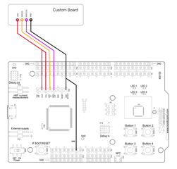
    Yes, it's possible to flash the Dongle using a DK and the SWDIO and SWDCLK pins on the Dongle. You'll need to solder on some pin headers on SWDIO, SWDCLK, VDD and GND in order to be to connect the DK like the image below to the Dongle (custom board in the image):

    You can also check out our Dongle Programming tutorial for more information on how to connect it to DKs or other debuggers. Although the tutorial is for the nRF5 SDK the connection method is the same. 

    Just to make sure, the light_bulb example builds successfully when you use the nRF52840dongle_nrf52840 build configuration, right?

    Can you try building and flashing the example to the Dongle using the method described here with West and nrfutil?

    Best regards,

    Simon

Reply
  • Hi

    Yes, it's possible to flash the Dongle using a DK and the SWDIO and SWDCLK pins on the Dongle. You'll need to solder on some pin headers on SWDIO, SWDCLK, VDD and GND in order to be to connect the DK like the image below to the Dongle (custom board in the image):

    You can also check out our Dongle Programming tutorial for more information on how to connect it to DKs or other debuggers. Although the tutorial is for the nRF5 SDK the connection method is the same. 

    Just to make sure, the light_bulb example builds successfully when you use the nRF52840dongle_nrf52840 build configuration, right?

    Can you try building and flashing the example to the Dongle using the method described here with West and nrfutil?

    Best regards,

    Simon

Children
  • 1. okay will try the pin connection - so this setup will allow me the debug the image flashed on the dongle?

    Just to make sure, the light_bulb example builds successfully when you use the nRF52840dongle_nrf52840 build configuration, right?

    2. Yes, the the example builds fine and generates a merged.hex which can also be flashed.  In fact i tested with only change of that PWM led and nothing else.  Can you test from your side as well?  Are there any additional setting to be done? This is not a problem with Zephyr as the blinky code runs fine on the dongle, so it must be zigbee

    Can you try building and flashing the example to the Dongle using the method described here with West and nrfutil?

    3. I could run via command prompt, but when I run the VS Code, the same commands are executed. How will this be different?  Please do check on the #2 and let us know if there are any additional settings to be changed KConfig maybe for flashing onto dongle?

Related