Only spi nodes accepted in /soc/spi@40023000/

I'm running in to the issue mentioned in the tile; "Only spi nodes accepted in /soc/spi@40023000/". I'm using nRF connect and built a driver for the TI ADS1291 analog front end but I'm facing this error and I'm unable to find any documentation. I've compared it as much as possible with the ADXL372 example but the in and outputs seem the same to me.

I added a ti,ads1291.yaml file at dts/bindings/ and added "set(DTS_ROOT dts)" to CMakeLists.txt with the following contents:

# A high level description of the device the binding applies to:
description: |
   This is the TI ADS1291

# Used to match nodes to this binding as discussed above:
compatible: "ti,ads1291"

include: spi-device.yaml

properties:
    int1-gpios:
      type: phandle-array
      required: false
      description: |
        The INT1 signal defaults to active low as produced by the
        sensor.  The property value should ensure the flags properly
        describe the signal that is presented to the driver.
s

I also added the ADS1291 by means of an overlay to the nrf52dk_nrf52832 devicetree:

&spi2 {
	cs-gpios = <&gpio0 4 GPIO_ACTIVE_LOW>;
	ads1291@0 {
		compatible = "ti,ads1291";
		reg = <0>;
		spi-max-frequency = <2000000>;
		label = "ADS1291";
		int1-gpios = <&gpio0 31 GPIO_ACTIVE_LOW>;
	};
};

I enabled my custom driver from prj.conf: 

CONFIG_ADS1291=y

The build system seems to pick up the config correctly:

 *   61  /soc/spi@40023000
 *   62  /soc/spi@40023000/ads1291@0
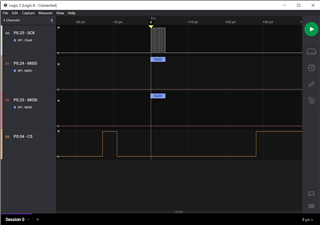
I've also attached a logic analyser to the GPIO pins don't see any SPI data. I do see SPI data when I flash the ADXL372 example.
I must have missed a config step somewhere, can anyone please help in pointing out what I missed?
Thanks
Parents
  • Hello!

    Can you show me how the spi2 node looks in your devicetree (in the build/zephyr/zephyr.dts file) when you have compiled the ADXL372 and the ADS1291 projects?

    If there is a difference it might help you spot what you have missed.

    On my end it looks like this in the ADXL372 project:

    spi2: arduino_spi: spi@40023000 {
    	#address-cells = < 0x1 >;
    	#size-cells = < 0x0 >;
    	reg = < 0x40023000 0x1000 >;
    	interrupts = < 0x23 0x1 >;
    	status = "okay";
    	label = "SPI_2";
    	compatible = "nordic,nrf-spi";
    	sck-pin = < 0x19 >;
    	mosi-pin = < 0x17 >;
    	miso-pin = < 0x18 >;
    	cs-gpios = < &gpio0 0x16 0x1 >;
    	adxl372@0 {
    		compatible = "adi,adxl372";
    		reg = < 0x0 >;
    		spi-max-frequency = < 0x7a1200 >;
    		label = "ADXL372";
    		int1-gpios = < &gpio0 0xb 0x0 >;
    	};
    };

    Best regards,

    Einar

  • Hi, thanks for looking in to this.

    For my custom project it looks like this:

    		spi2: arduino_spi: spi@40023000 {
    			#address-cells = < 0x1 >;
    			#size-cells = < 0x0 >;
    			reg = < 0x40023000 0x1000 >;
    			interrupts = < 0x23 0x1 >;
    			status = "okay";
    			label = "SPI_2";
    			compatible = "nordic,nrf-spi";
    			sck-pin = < 0x19 >;
    			mosi-pin = < 0x17 >;
    			miso-pin = < 0x18 >;
    			cs-gpios = < &gpio0 0x4 0x1 >;
    			ads1291@0 {
    				compatible = "ti,ads1291";
    				reg = < 0x0 >;
    				spi-max-frequency = < 0x1e8480 >;
    				label = "ADS1291";
    				int1-gpios = < &gpio0 0x1f 0x1 >;
    			};
    		};

    The example looks similar to yours but some of the gpios are different. 

    		spi2: arduino_spi: spi@40023000 {
    			#address-cells = < 0x1 >;
    			#size-cells = < 0x0 >;
    			reg = < 0x40023000 0x1000 >;
    			interrupts = < 0x23 0x1 >;
    			status = "okay";
    			label = "SPI_2";
    			compatible = "nordic,nrf-spi";
    			sck-pin = < 0x19 >;
    			mosi-pin = < 0x17 >;
    			miso-pin = < 0x18 >;
    			cs-gpios = < &gpio0 0x16 0x1 >;
    			adxl372@0 {
    				compatible = "adi,adxl372";
    				reg = < 0x0 >;
    				spi-max-frequency = < 0x7a1200 >;
    				label = "ADXL372";
    				int1-gpios = < &gpio0 0xb 0x0 >;
    			};
    		};

    I don't see any significant differences between my custom one and the example..

  • Hm, I cannot see anything obvious missing.

    I assume you've already double and triple checked that the gpio pins you've defined in the devicetree correspond with how your sensor is connected?

    I find it strange that you don't see anything when measuring the pins. Are any of your function calls returning error codes that could give you hints?

    -Einar

  • I see the following:

    Device ADS1291 is not ready
    [00:00:00.000,427] [1;31m<err> ADS1291: Failed to read id. Expected 0x2A got 0x0[0m
    The first log line is generated by
    const struct device *afe_dev = DEVICE_DT_GET_ANY(ti_ads1291);
    if (!device_is_ready(afe_dev)) {
    	printk("Device %s is not ready\n", afe_dev->name);
    }
    The second log line is generated by:
    static int ads1291_init(const struct device *dev)
    {
        struct ads1291_data *data = dev->data;
        const struct ads1291_dev_config *cfg = dev->config;
        int ret;
    
        data->bus = device_get_binding(cfg->spi_port);
        if (!data->bus) {
            LOG_ERR("SPI device not found: %s", cfg->spi_port);
            return -EINVAL;
        }
    This code uses the following SPI config in the config struct which I copied from the ADXL372 example:
    static const struct ads1291_dev_config ads1291_config = {
    
        .spi_port = DT_INST_BUS_LABEL(0),
        .spi_slave = DT_INST_REG_ADDR(0),
        .spi_max_frequency = DT_INST_PROP(0, spi_max_frequency),
    #if DT_INST_SPI_DEV_HAS_CS_GPIOS(0)
        .gpio_cs_port = DT_INST_SPI_DEV_CS_GPIOS_LABEL(0),
        .cs_gpio = DT_INST_SPI_DEV_CS_GPIOS_PIN(0),
        .cs_flags = DT_INST_SPI_DEV_CS_GPIOS_FLAGS(0),
    #endif
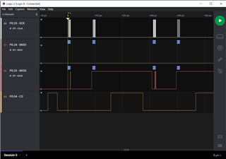
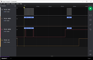
    I've had a second look with the logic analyser and it does seem to do something, but I also expect to see MOSI data. It does seem to recognize the 'spi-max-frequency = 2 MHz' which I set in the device tree under the sensor.
    For example, this is how the ADXL372 example looks with the same pin configuration as my project:
  • I see

    glenn-ide said:
    Device ADS1291 is not ready
    [00:00:00.000,427] [1;31m<err> ADS1291: Failed to read id. Expected 0x2A got 0x0

    I suspect dealing with these errors would solve your problem, maybe there should be a difference in the SPI config that you've forgotten?

    Any idea where "Expected 0x2A" comes from?

    Have you tried putting small sleeps at critical points of your initialization, such as between DEVICE_DT_GET_ANY and device_is_ready?

    -Einar

  • Sorry, I didn't look close enough at the messages. You're right the second message is generated by a different bit of code.

    Upon closer inspection it seems my spi code was doing something funky. I've now fixed it and it does write data:

    Device ADS1291 is not ready
    [00:00:00.000,366] [0m<dbg> ADS1291.ads1291_bus_access: REG Read for register 0x00 resulting in 0x20 sent[0m
    [00:00:00.000,366] [0m<dbg> ADS1291.ads1291_bus_access: Number of registers to read/write 2[0m
    [00:00:00.000,457] [1;31m<err> ADS1291: Failed to read id. Expected 0x2A got 0x00[0m
     
    The error message which started this post still remains but at least I can now continue development. 
    Thanks for making me look deeper in to this.
  • Glad to see you figured it out!

    Good luck on your project, best regards,

    Einar

Reply Children
No Data
Related