
Hi
I'm working with an nrf52840-dk on NCS 1.8.0.
I'm attempting to interface the board with an LS7366R quadrature counter over SPI; however, I'm not receiving any count information when it is requested. I'm an auditor, not an engineer, so I may be interpreting the data sheet incorrectly, so I was hoping I could get a sanity check on the test code I threw together to see if there is anything obviously with my configuration. Everything is hardcoded at the moment.
The data sheet for the IC is here - https://lsicsi.com/datasheets/LS7366R.pdf - and is fairly straight forward as to how it operates, or at least I thought.
Specifically, though, I'm using the breakout here: www.superdroidrobots.com/.../product=2397
#include <stdlib.h>
#include <stdio.h>
#include <string.h>

#include <zephyr.h>
#include <logging/log.h>

#include <drivers/spi.h>

#define CLR_CNTR 0x20
#define READ_MDR0 0x48
#define READ_MDR1 0x50
#define READ_CNTR 0x60
#define WRITE_MDR0 0x88
#define COUNTER_4X_QUAD 0x03

LOG_MODULE_REGISTER(main, LOG_LEVEL_INF);

struct spi_cs_control spi_cs = {
	.gpio_pin = DT_GPIO_PIN_BY_IDX(DT_NODELABEL(spi1), cs_gpios, 0),
	.gpio_dt_flags = GPIO_ACTIVE_LOW,
	.delay = 0,
};

static struct spi_config spi_cfg = {
	.operation = SPI_OP_MODE_MASTER | SPI_TRANSFER_MSB | SPI_LINES_SINGLE | SPI_WORD_SET(8),
	.frequency = 2000000,
	.slave = 0,
	.cs = &spi_cs,
};

const struct device *spi_dev;


void spiInit(void)
{
	LOG_INF("Initializing SPI 1\n");

	const char* const spiName = "SPI_1";
	spi_cs.gpio_dev = device_get_binding("GPIO_1");
	if (spi_cs.gpio_dev == NULL)
	{
	    LOG_ERR("Couldn't get GPIO_1 device\n");
	}

	spi_dev = device_get_binding(spiName);

	if (spi_dev == NULL) {
		LOG_ERR("Couldn't get %s device\n", spiName);
		return;
	}
    LOG_INF("SPI 1 Initialized\n");
}

void setMDRO(void)
{
	//MDRO is always a one byte register.  Expects 1 byte of data (i.e., settings).  Second tx byte for command.
	int err;
	static uint8_t tx_buffer[2];

	const struct spi_buf tx_buff = {
		.buf = tx_buffer,
		.len = sizeof(tx_buffer)
	};

	const struct spi_buf_set tx = {
		.buffers = &tx_buff,
		.count = 1
	};

	tx_buffer[0] = WRITE_MDR0;
	tx_buffer[1] = COUNTER_4X_QUAD;  //other default settings on register are fine

	err = spi_write(spi_dev, &spi_cfg, &tx);
	if(err)
	{
		LOG_ERR("Failed to set MDR0: %d\n", err);
	} else
	{
		LOG_INF("MDR0 is setup\n");
	}
}

void readMDRO(void)
{
	int err;
	static uint8_t tx_buffer[1];

	const struct spi_buf tx_buff = {
		.buf = tx_buffer,
		.len = sizeof(tx_buffer)
	};

	const struct spi_buf_set tx = {
		.buffers = &tx_buff,
		.count = 1
	};

	static uint8_t rx_buffer[1];

	const struct spi_buf rx_buff = {
		.buf = rx_buffer,
		.len = sizeof(rx_buffer)
	};

	const struct spi_buf_set rx = {
		.buffers = &rx_buff,
		.count = 1
	};

	tx_buffer[0] = READ_MDR0;

	err = spi_transceive(spi_dev, &spi_cfg, &tx, &rx);
	if(err)
	{
		LOG_ERR("Read MDR0 Failed): %d\n", err);
	} else
	{
		LOG_INF("Read MDR0\n");
	}
}

void readCounter(void)
{
int err;
	static uint8_t tx_buffer[1];
	LOG_INF("sizeof(tx_buffer) = %i", sizeof(tx_buffer));

	const struct spi_buf tx_buff = {
		.buf = tx_buffer,
		.len = sizeof(tx_buffer)
	};

	const struct spi_buf_set tx = {
		.buffers = &tx_buff,
		.count = 1
	};

	//counter hardcoded at 32 bits via MDR1 default settings, should get 4 bytes of data back
	static uint8_t rx_buffer[4];

	const struct spi_buf rx_buff = {
		.buf = rx_buffer,
		.len = sizeof(rx_buffer)
	};

	const struct spi_buf_set rx = {
		.buffers = &rx_buff,
		.count = 1
	};

	tx_buffer[0] = READ_CNTR;

	err = spi_transceive(spi_dev, &spi_cfg, &tx, &rx);
	if(err)
	{
		LOG_ERR("Read Counter Failed): %d\n", err);
	} else
	{
		LOG_INF("Read Counter\n");
	}
}

void main(void)
{
	spiInit();
	setMDRO();
	readMDRO(); //no error, but no information provided either.
	while (1)
		{
			readCounter(); //no error, but no information provided either.
			printk("\r\n");
			k_sleep(K_MSEC(4000));
		}
}

// void setMDR1(void)
// {
// 	/* Register goes to 0 at powercycle (i.e., using default settings: four byte counter, counter enabled)*/
// }

// void setDTR(void);
// {
	// NA for these hardcoded settings
	// DTR bytes vary by counter byte setting:  32 bit mode -> 32 bit register
// }

// void clearSTR(void)
// {
		/*clears on powercycle */
// }
I'm not receiving any errors when reading the registers, but I'm also not getting back any information. For example, when requesting the counter value (0x60), I see the following:
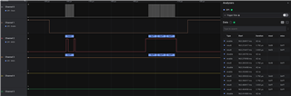
The image also shows the MDR0 read attempt (0x48) on the right. Essentially, I'm not seeing any movement on the MISO, which makes me think I'm not interpreting something correctly in the Zephyr docs.
/* nrf52840dk_nrf52840.overlay */
/ {
	chosen {
		zephyr,entropy = &rng;
	};
};
&spi3 {
	compatible = "nordic,nrf-spim";
	status = "disabled";
};
&spi1 {
	compatible = "nordic,nrf-spim";
	status = "okay";
	cs-gpios = <&gpio1 12 GPIO_ACTIVE_LOW>; //p1.12
	sck-pin = <47>;							// p1.15
	miso-pin = <46>;  						// p1.14
	mosi-pin = <45>; 						// p1.13
};
/* pjr.conf */
CONFIG_SPI=y
CONFIG_LOG=y
CONFIG_SERIAL=y
Thanks

