This discussion has been locked.
You can no longer post new replies to this discussion. If you have a question you can start a new discussion

Low power on the nRF9160

Hi, 

I recently designed a prototyping board featuring the nRF9160, which we got made for a couple of reasons. 

  • To have multiple boards to test with
  • Potential to have multiple engineers working with them
  • Long term testing of potential products
  • To see if our production equipment could successfully populate such a small device. 

The good news is, we successfully managed to populate a panel, and all 8 of the PCBs are are programmable. No short circuits between pins on the device that can be seen under a microscope. As its an LGA component, there is a chance that there could be shorts underneath the board, but we do not own x-ray inspection equipment to be able to see this. 

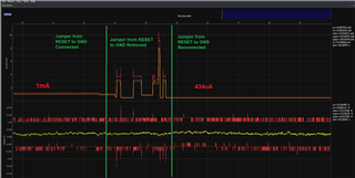
The main idea for our prototype board is a datalogger, that sends data periodically over LTE networks using MQTT, so low power is an absolute must. I noticed when using our current code we  see constant currents of around 3mA at its lowest, even when its in Power Saving Mode (PSM). So I looked into this a bit more thoroughly.  

I saw this question posted below, and tried to recreate his code, following an example through a link he posted. I also tried multiple different things with the GPIO configuration - ended up making them all high-z. 

https://devzone.nordicsemi.com/f/nordic-q-a/63745/lowering-the-power-consumption-of-nrf9160-mqtt_simple-ncs-1-3-0

Even when running this code, I was seeing about 2.7mA constant current. So around 500x more than expected. 

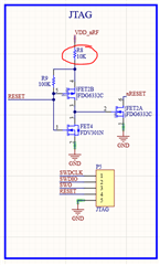
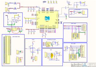
Ok, so now I thought I must've messed up something on the design, so I take off the 3V regulator circled in the schematic, and removed the pullup resistors on the SDA/SCL lines, so  the only thing being powered is the nRF9160. I now get 2.61mA

Is there something fundamentally wrong with my schematic to get into a low power idle state? Could the reserved pins underneath the package cause a high constant current if shorted together somewhere? Is the code missing anything to be in low power?

Schematic and code below

/*
 * Copyright (c) 2018 Nordic Semiconductor ASA
 *
 * SPDX-License-Identifier: LicenseRef-BSD-5-Clause-Nordic
 */

#include <zephyr.h>
#include <stdio.h>
#include <drivers/uart.h>
#include <string.h>
#include "hal/nrf_gpio.h"

/**@brief Recoverable BSD library error. */
void bsd_recoverable_error_handler(uint32_t err)
{
	printk("bsdlib recoverable error: %u\n", err);
}

void main(void)
{	
	for(int i=0;i<32;i++){
		nrf_gpio_cfg_input( i, NRF_GPIO_PIN_NOPULL);
	}

	NRF_UARTE0->ENABLE = 0;
    NRF_UARTE1->ENABLE = 0;
    
	k_sleep(K_SECONDS(6));

	k_cpu_idle();
}

Thanks, 

Damien

Parents
  • Hello,

    you should put the modem to sleep as well. If you're unsure how to do this, all necessary details are explained in this blog post.

  • Hi Hakon, 

    For some reason I thought it would automatically be off, and in the process of testing this I actually found what was going on. I always suspect there is loss through the JLink debugger so I always unplug it after I have flashed the board. This time, when I removed VRef the current went down to ~500uA, when I removed the reset line, it jumped up to 3mA again. 

    Seems like the JLink pulls down reset but it goes high when removed from the JLink. Looking at the schematic I can see why, and looking at datasheet, I can see that nReset shouldnt be pulled higher than 2.2V. 

    Now I expected if I reset the board, and put a jumper across RESET and GND, then this would mean I should see ~500uA after startup, but thats not what happened. 

    As you can see in the image below, I got just over 1mA initially, but if I took the jumper off and replaced it again it did go down to 434uA. This seems odd behaviour to me, and can't really understand why that happening. Is there a resource that shows how the nReset line should be connected up? I just copied the nRF9160DK schematic for the reset stuff, with a slight change in what FETs are used as they were ones we use elsewhere already, but I cant see why they would cause much issue, and they seem to be doing exactly what I expect.

    Any thoughts would be appreciated. 

    Thanks, 

    Damien

  • Hi Damien,


    DamoL said:
    As you can see in the image below,

    looks like the image was not included. 


    The nRESET is pulled high to 2.2V internally
    https://infocenter.nordicsemi.com/topic/ps_nrf9160/pmureset.html?cp=2_0_0_4_4_1#pin_reset 


    Are you flashing the device with a program that puts in system off ? Like shown in the blog Håkon refers to. 

    Regards,
    Jonathan

  • Hi Jonathan

    Apologies, I have added image in now. 

    I am flashing with the code in the OP. It's using k_cpu_idle()

    Thanks, 

    Damien

Reply Children
  • Hi,

    Thanks for the clarification. 

    Using the nrf9160DK as a reference is fine, can also use the Thingy91 as a reference. But it is always good to follow the HW design and verification guidelines also. 

    #include <modem/lte_lc.h>
    void main(void)
    {
    lte_lc_power_off();
    k_sleep(K_MSEC(1000));
    NRF_REGULATORS->SYSTEMOFF = 1;
    }


    How does it preform i system off, are you able to get sub 5uA? Would want to know  that the measurement setup preforms as expected.  What modem firmware are you using?

    Regards,
    Jonathan

  • Hi Jonathan, 

    I have tried this code and get around 600uA. Now if I remove this resistor R8 (image), it drops to 96uA, and if I remove the 3V supply, it gets down to 5-6uA.

    The extra current when the 3V supply is present, I can kind of understand. I'm using P-Channel FETS, so I assume in system-off mode they will be in an ON state, and even when nothing is connected to the output there could still be some loss. 

    Thanks, 

    Damien

  • I still think the 600uA is unusually high. So from what yo describe there seems to be something on the 3V line that is causing a unusaly high current draw. Was thinking that the op-amp might contribute to the draw and the active gps, but that still does not account for the high value i think. 

    What state is the GPIO that is driving your fets... see you tried making all high z. 

    Do you have a nrf52 or som other chip on the pcb also? where does RESET line go? 

    the op-amp is also driven by 3V but if on it has a max uA of 230uA in worst case, from what i can see in datasheet. What is the battery supply voltage?

    I will ponder on this and get back to you. 

    Regards,
    Jonathan

  • Yes I agree 600uA does seem excessive. Although I think there may have been a short under the 10k resistor R8, as it reduced to 96uA when I removed it. I just replaced it to confirm it was still 600uA and it stayed at 96uA, so that's a positive start. 

    What state is the GPIO that is driving your fets... see you tried making all high z. 

     The GPIOs are reading 3V as they are pulled up externally. Not sure how I should be configuring them tbh. If I use the code you posted which doesn't configure them, I get 96uA. If I configure them as hi-z its about 130uA.

    Do you have a nrf52 or som other chip on the pcb also? where does RESET line go? 

    No, the RESET net goes to the JTAG header and nRESET net goes to the nRF9160 nRESET pin through a 1K resistor and 100uF capacitor. The whole schematic is attached on the OP. 

    The op-amp is a direct copy from another design, so I doubt its an inherent design flaw there. I checked the shutdown pin was low and it is. 

    The board is currently using a 3.6V supply.

    Thanks,

    Damien

  • DamoL said:
    I get 96uA

    I am a bit interested in this number.... i have seen on rear ocations that a DK can show values close to 90uA.. i have seen around 70-80uA after flashing the file one some devices. But after wiping the device and power cycle, then flash and power cycle the consumption has gone down to normal levels. 

    What modem firmware are you using?


    Regards,
    Jonathan

Related