
Hi, I made a custom PCB.
I use a Revision 2 MCU.
The antenna is printed. I didn't used the chip antenna.
Sorry for not showing both the full schematic and the Gerber file.
I have downloaded the DTM firmware from SDK 7.2.
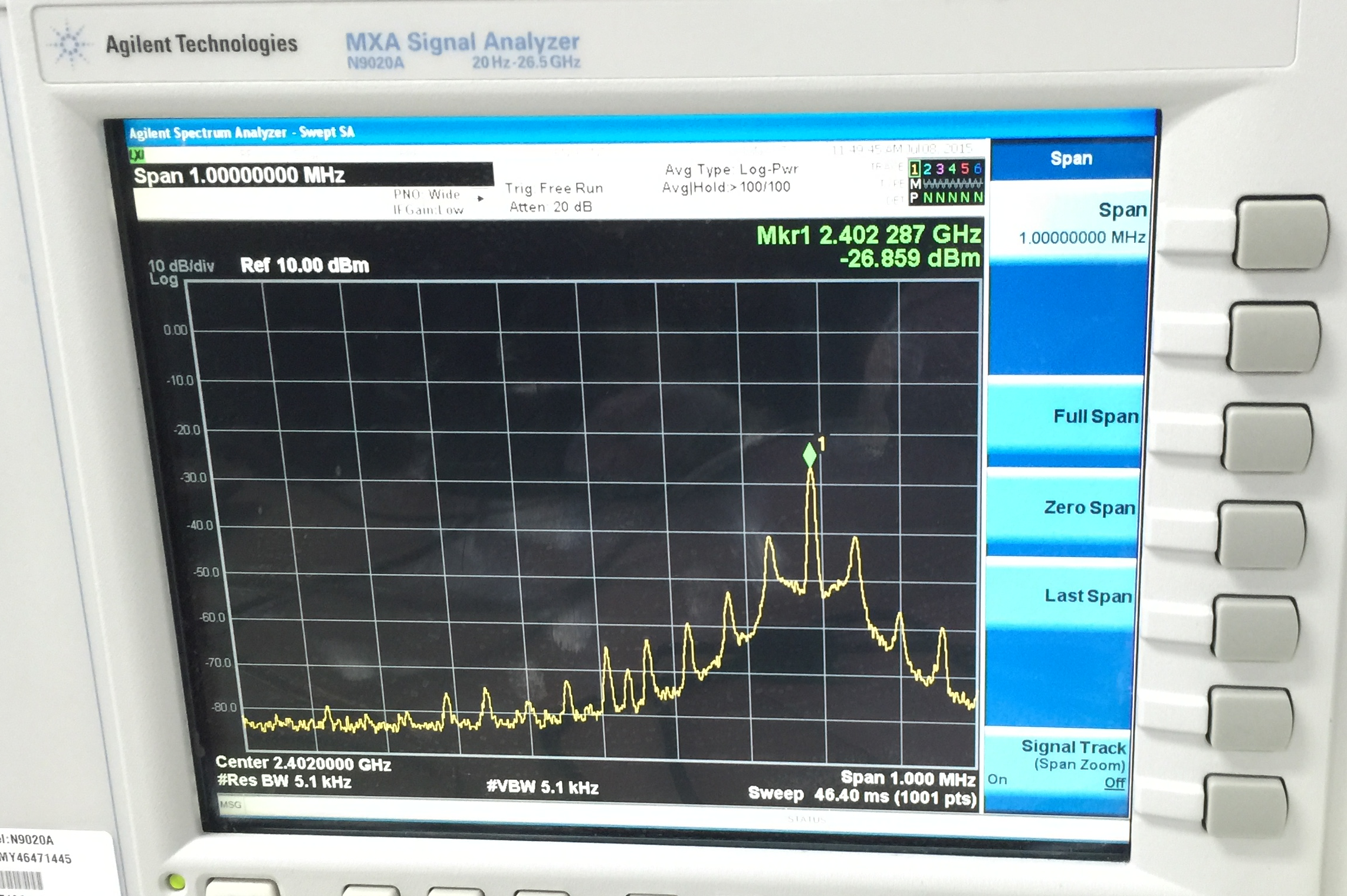
The next picture is the frequency when it received command to do TX test of channel 0 (Advertising channel 37).
While testing for CE (Conformite Europeenne) and KC (Korea Certification),
the result was quite poor when I used 12pF for decoupling the 16MHz crystal.
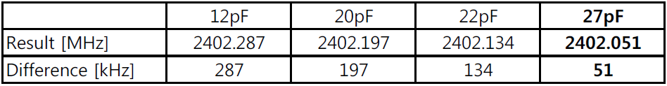
So I changed the caps. When I use the 27pF cap, it finally matched the frequencies.
The cap is the Murata GRM1555C1H270J.
But the biggest problem is that the TX power value is -16.90dBm.
/*******************/
So my questions are,
- How could the PCA10001 use 12pF?
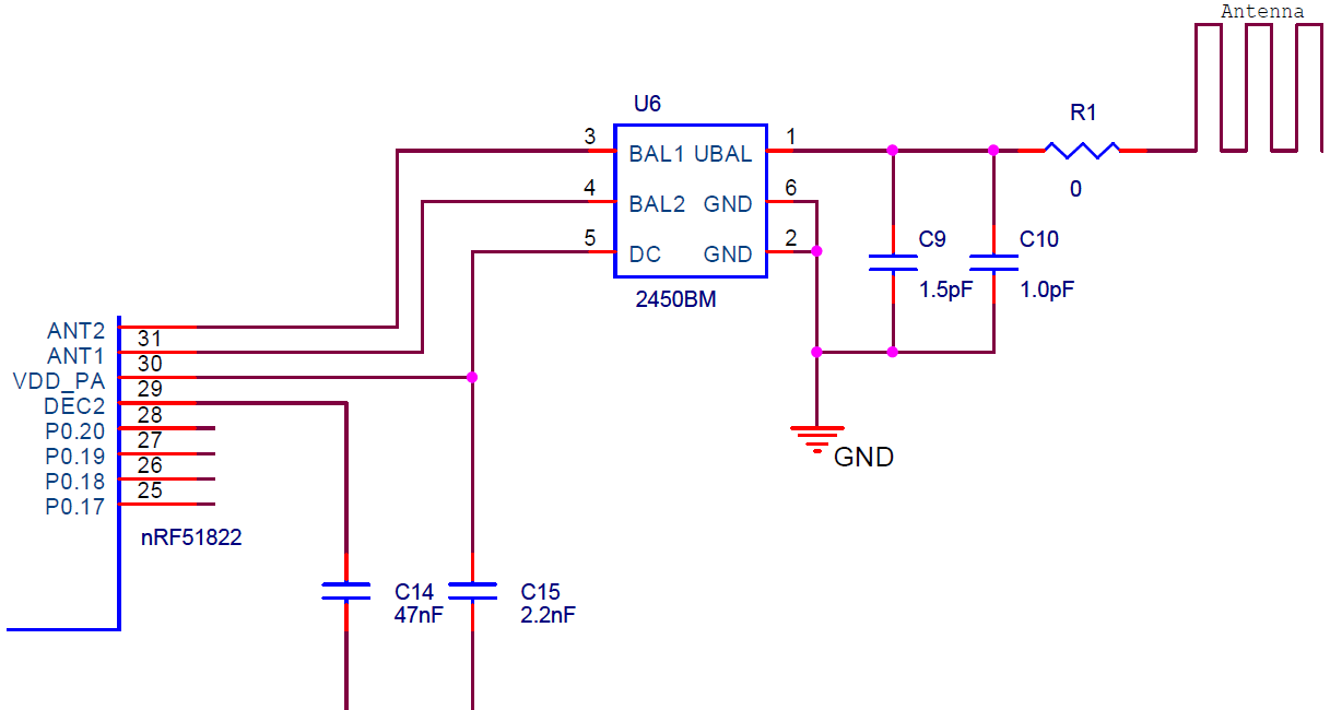
Comparing with the PCA10001's schematic,
I replaced the inductor L1 and L2 to the balun (datasheet link).
After I changed the cap to 27pF, my board and smart phones pair each other.
Does the cap size for decoupling 16MHz crystal varies case by case?
- The TX value and the 16MHz crystal are independent, is it?
What are the reasons for poor level of TX?
-Regards, Mango922
