This discussion has been locked.
You can no longer post new replies to this discussion. If you have a question you can start a new discussion

BLE example for custom board with NRF52820 and no 32Khz xtal

Hello all,

This is my first project using Nordic chips and my first project using BT. A lot of firsts :)


I have made a custom board using nRF52820 chip. The board is 4 layer 0.8mm thick board 80mm x 50mm. I have used the PCB manufacturer's calculator to set the trace with for the 50 ohm impedance. The antenna I am using is Johanson Technology 2450AT43A100E. I do not have low frequency xtal on the board. You can see may schematics and the layout I have used for this board bellow.

Layout

Schematic

I am programming the board using nRF52833-DK. So far I got SPI, TWI and USB to work on the board, but I am struggling with the RF part. 

For my base project I am using the "usbd_ble_uart". I can successfully connect and RX/TX data using my phone and the DK. I have looked at questions already posted on the forum and I figured out that I need to change the LF clock source to the internal RC oscillator. The changes I have made to the "sdk_config.h" files are the following. SoftDevice version is s140 and the SDK is v17

#ifndef NRFX_CLOCK_CONFIG_LF_SRC
#define NRFX_CLOCK_CONFIG_LF_SRC 0
#endif

#ifndef CLOCK_CONFIG_LF_SRC
#define CLOCK_CONFIG_LF_SRC 0
#endif

// <o> NRF_SDH_CLOCK_LF_SRC  - SoftDevice clock source.
 
// <0=> NRF_CLOCK_LF_SRC_RC 
// <1=> NRF_CLOCK_LF_SRC_XTAL 
// <2=> NRF_CLOCK_LF_SRC_SYNTH 

#ifndef NRF_SDH_CLOCK_LF_SRC
#define NRF_SDH_CLOCK_LF_SRC 0
#endif

// <o> NRF_SDH_CLOCK_LF_RC_CTIV - SoftDevice calibration timer interval. 
#ifndef NRF_SDH_CLOCK_LF_RC_CTIV
#define NRF_SDH_CLOCK_LF_RC_CTIV 16
#endif

// <o> NRF_SDH_CLOCK_LF_RC_TEMP_CTIV - SoftDevice calibration timer interval under constant temperature. 
// <i> How often (in number of calibration intervals) the RC oscillator shall be calibrated
// <i>  if the temperature has not changed.

#ifndef NRF_SDH_CLOCK_LF_RC_TEMP_CTIV
#define NRF_SDH_CLOCK_LF_RC_TEMP_CTIV 2
#endif

// <o> NRF_SDH_CLOCK_LF_ACCURACY  - External clock accuracy used in the LL to compute timing.
 
// <0=> NRF_CLOCK_LF_ACCURACY_250_PPM 
// <1=> NRF_CLOCK_LF_ACCURACY_500_PPM 
// <2=> NRF_CLOCK_LF_ACCURACY_150_PPM 
// <3=> NRF_CLOCK_LF_ACCURACY_100_PPM 
// <4=> NRF_CLOCK_LF_ACCURACY_75_PPM 
// <5=> NRF_CLOCK_LF_ACCURACY_50_PPM 
// <6=> NRF_CLOCK_LF_ACCURACY_30_PPM 
// <7=> NRF_CLOCK_LF_ACCURACY_20_PPM 
// <8=> NRF_CLOCK_LF_ACCURACY_10_PPM 
// <9=> NRF_CLOCK_LF_ACCURACY_5_PPM 
// <10=> NRF_CLOCK_LF_ACCURACY_2_PPM 
// <11=> NRF_CLOCK_LF_ACCURACY_1_PPM 

#ifndef NRF_SDH_CLOCK_LF_ACCURACY
#define NRF_SDH_CLOCK_LF_ACCURACY 1
#endif


But still I cannot connect with phone to the custom board. I cannot see it listed in the BT devices at all. 

How can I determine if it is a software or a hardware issue? Is there something else I need to change to the config? I have read the post for migrating code to the nRF52820 and yes the preprocessor directives are set correct and the memory sizes are adjusted.  

There are a lot of logging options set up in the examples, is any of it going to be useful?

As tools go I have a scope but unfortunately I do not have a spectrum analyzer at my disposal.  

If there is example specially made for the nRF52820 would be great! This way I could see if it is my design to blame or just some tricky config.

All the best,
Mitko

  • You should create a new schematic and layout that follow the reference layout closely (e.g. make sure the clearance, width, length, traces and cut-put to ground and vias are the same around the matching network). The components values in the matching network is for instance 1pF, with your current layout and clearance to ground, then the impact of tolerance of the pcb can have a significant impact on the capacitance, so you may get very variable result board to board. So please check: https://infocenter.nordicsemi.com/topic/ps_nrf52820/ref_circuitry.html#concept_hf5_hzm_fs 

    All that said, to make sure the firmware can run on the nRF52820 you should check out:
    https://infocenter.nordicsemi.com/topic/sdk_nrf5_v17.1.0/nrf52820_user_guide.html 

    I recommend to get an nRF52-DK for comparison during development if you haven't already. Logging is very useful, for instance to check if the code may get stuck/assert somwhere, if you for instance have UART logging make sure the RXD pin is pulled high (e.g. by 10khom pull up resistor) if not connected high externally by other means.

    Kenneth

  • Hi Kenneth,

    The schematic is the same as per the examples provided. The LF crystal is marked as optional, so I omitted it. In the datasheet is said that I can skip the external crystal and still use the radio. I took into account that and I have used the internal RC oscillator (see the code above)

    The layout is as close as possible, but we are developing custom boards and I don't think it is reasonable to expect 1 to 1 match. The range requirements for my device are not vary demanding. It should work from 0.5m to 1m with nothing in the way. 

    I do have a development kit i.e. nRF52833-DK witch is recommended for the nRF52820, but it uses a different chip with emulation. 

    I already told you that I have read the nrf52820 user guide I got the USB, TWI and SPI working. 

    Do you have example code that you have ran on actual nrf52820 chip, not nRF52833 with emulation. If yes can you provide the code?

    I really would like to know if there are any register values that I could check to make sure that the radio IP is initialized correctly. Or may be a set of functions that the code should go through, 

    Any information like this would be helpful. 

  • I suggest to use the https://infocenter.nordicsemi.com/topic/sdk_nrf5_v17.1.0/ble_sdk_app_nus_eval.html as starting point. If you open the pca10100e project, the only change you need to do is as described in the user guide: "If you have developed your application using the emulated project as a starting point, there is only one step you need to perform before you can run it natively on nRF52820: in your IDE, remove the DEVELOP_IN_NRF52833 and NRFX_COREDEP_DELAY_US_LOOP_CYCLES defines from the compile flags."

    Also, you may need to consider adding a 10kohm pull-up the RXD pin, to avoid the pin floating which cause various framing errors on the UART that can assert the code.

    My suggestion for debugging futher (if you don't have a spectrum analyzer):

    1. Measure current consumption when entering advertising mode, as described here:
    https://infocenter.nordicsemi.com/topic/ug_nrf52833_dk/UG/dk/hw_measure_current.html 

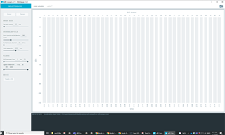
    2. Try to use the RSSI viewer to look if there is any carrier:

    3. When using the softdevice it's not possible to single step or set breakpoints in your project, since this will quickly assert the project. However it should be possible to find if the code is stuck or hanging somewhere, e.g. by logging to UART or RTT and/or use some kind of LED's and trial and error.

    Kenneth

  • Thank you Kenneth!

    I will do this. I also found Panasonic ENW89857AXKF development board. I will run the code for the radio on it to determine if it is a hardware problem or a software one and I will get back to you.

    Cheers!
    Mitko 

  • Sounds good. I forgot that you will need to do the changes to the 32k source as you wrote in the first post.

    Kenneth

Related