nrf9160 DK -- Side effects of external power supply P21

Dear Nordic Support Team,

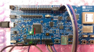
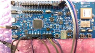
I am developing an application for the nrf9160 DK version 1.0.x (nrf connect sdk 1.8.0 and modem firmware 1.3.1). The application depends on other hardware periphery connected to the board via UART and SPI interfaces. The periphery is powered via the board (I use the 5 V pin, a VDD pin and several ground  pins). SW9 is switched to 3V. I have a power adapter which delivers 5 V (max. 2 A) via a USB plug or two pins.

So far, I test my application only while supplying the nrf9160 DK via it's USB interface (from my laptop or with the aforementioned power adapter). All tests made with this setup worked as expected. However, when I supply the nrf9160 via it's external power supply interface (P21), using the pins instead of the USB plug of my power adapter, the application does not wok anymore.

I noticed one difference on the board so far. If I supply the nrf9160 DK via its USB interface, the power between a ground pin and the 5 V pin is, as expected, approximately 5 V. However, if I supply the nrf9160 DK via P21, the power between a ground pin and the 5 V pin is close to 0 V. With this fact in mind, it does not surprise me that my application fails, since my periphery isn't supplied anymore.

I have three questions in this context:

  1. Can you please help me to understand the behavior I am seeing?
  2. What other side effects occur when not supplying the board via its USB interface?
  3. What do I have to do when I just want the board to behave the same regardless of the power supply interface in use or rather, how do I disable the side effects and get my application running while supplying the board via P21?

I attached my nrf9160dk_nrf9160_ns.overlay file to provide a little context on my hardware periphery in use.

nrf9160dk_nrf9160_ns.overlay

Thank you for your time. Please don't hesitate to ask if you have any questions.

Cheers,
Sebastian

Parents
  • Hi,


    When supplying voltage through P21, it is important that you do not have any other power sources plugged in. Here's the diagram for the power supply part of the DK:

    https://infocenter.nordicsemi.com/topic/ug_nrf91_dk/UG/nrf91_DK/hw_power_supply.html?cp=2_0_5_3_2


    However, if I supply the nrf9160 DK via P21, the power between a ground pin and the 5 V pin is close to 0 V. With this fact in mind, it does not surprise me that my application fails, since my periphery isn't supplied anymore.

    Which VDD pin are you measuring?

    • What other side effects occur when not supplying the board via its USB interface?

    One thing is that you are powering the whole DK, meaning that any blinking LEDs will also count towards the total current consumption as seen from the battery source (or in this case, usb charger), and the debugger IC is switched off (no UARTs).

    What do I have to do when I just want the board to behave the same regardless of the power supply interface in use or rather, how do I disable the side effects and get my application running while supplying the board via P21?

    If you disconnect the USB cable, then provide >3V to P21, the device should start up. Remember that the power switch must be in the "ON" position.

    You could flash the nRF with a simpler fw, like blinky, and see if this blinks an LED when externally powered to eliminate the firmware-aspect.


    Kind regards,

    Håkon

  • Hi Håkon,

    thank you for your reply.

    I have attached two photos which show the working setup (scenario 1, supply via USB) and the not working setup (scenario 2, supply via P21). These setup only differ with respect to the power supply in use.

    When supplying voltage through P21, it is important that you do not have any other power sources plugged in.

    Yes. I supply the board either via USB xor via P21.

    Which VDD pin are you measuring?

    I use both, a Pin labeled VDD (green arrow in the scenario 1 picture) and a Pin labeled 5 V (red arrow in the scenario 1 picture) to supply the periphery attached to the board. The pin labeled VDD behaves as expected in both scenarios. It provides a power of 3 V. However, the pin labeled 5 V only provides a power of 5 V if the board is supplied via USB. If the board is supplied via P21, the pin labeled 5 V provides a power of 0 V.

    and the debugger IC is switched off (no UARTs)

    Are you saying that only the routing to the virtual COM-ports is disabled if the board is supplied via P21 or are you really meaning that all three UART interfaces are disabled, even if they are routed from pins (say P0.23 and P0.24)  to the nrf9160 SiP?
    This would be another reason why my firmware fails, since on of the attached peripheral devices tries to communicate with the nrf9160 SiP via UART 2 (tx-pin P0.23, rx-pin = P0.24).

    Remember that the power switch must be in the "ON" position.

    Thank you for pointing that out. However, I assure you that I always remember to switch the board on before I expect it to do anything. :-P

    You could flash the nRF with a simpler fw, like blinky, and see if this blinks an LED when externally powered to eliminate the firmware-aspect.

    I am confided that this is not a firmware issue since the firmware is well tested and works as expected when the board is powered via USB (weather it is powered by a Laptop or a USB power adapter). However the firmware does behave as expected if the board is powered via P21. Thus I suspect that the hardware behaves different if the power supply changes. This is supported by my power measurement of the pin labeled 5 V and your statement that the UARTs are switched of.

    I hope I could clarify my case. My questions still remains. What can be done to get around the side effects when supplying the nrf9160 DK via P21.

    Scenario 1, everything works, supply via USB:

    Scenario 2, not working, supply via P21:

  • Hi,


    Thank you for the detailed description of your setup.

    Sebastian Stein said:
    I use both, a Pin labeled VDD (green arrow in the scenario 1 picture) and a Pin labeled 5 V (red arrow in the scenario 1 picture) to supply the periphery attached to the board. The pin labeled VDD behaves as expected in both scenarios. It provides a power of 3 V. However, the pin labeled 5 V only provides a power of 5 V if the board is supplied via USB. If the board is supplied via P21, the pin labeled 5 V provides a power of 0 V.

    The "5V" pin is the VBUS line, so this will only be provided when powering the board through USB.

    The input voltage to the nRF is provided through the "VDD nRF" pin on pin header P20.


    Note that "VDD" is 1.8V or 3V depending on the position of the "VDD_IO" switch.


    Kind regards,

    Håkon

Reply
  • Hi,


    Thank you for the detailed description of your setup.

    Sebastian Stein said:
    I use both, a Pin labeled VDD (green arrow in the scenario 1 picture) and a Pin labeled 5 V (red arrow in the scenario 1 picture) to supply the periphery attached to the board. The pin labeled VDD behaves as expected in both scenarios. It provides a power of 3 V. However, the pin labeled 5 V only provides a power of 5 V if the board is supplied via USB. If the board is supplied via P21, the pin labeled 5 V provides a power of 0 V.

    The "5V" pin is the VBUS line, so this will only be provided when powering the board through USB.

    The input voltage to the nRF is provided through the "VDD nRF" pin on pin header P20.


    Note that "VDD" is 1.8V or 3V depending on the position of the "VDD_IO" switch.


    Kind regards,

    Håkon

Children
  • Hi Håkon,

    thank you for your response.

    The "5V" pin is the VBUS line, so this will only be provided when powering the board through USB.

    Ok. That is good to know. That means, that I have to change my setup to compensate for this.

    The input voltage to the nRF is provided through the "VDD nRF" pin on pin header P20.

    Can you please further elaborate were you are going with that statement?

    Are you saying that only the routing to the virtual COM-ports is disabled if the board is supplied via P21 or are you really meaning that all three UART interfaces are disabled, even if they are routed from pins (say P0.23 and P0.24)  to the nrf9160 SiP?

    Can you please comment on this question?

    Thank you.

    Kind regards,
    Sebastian

  • Hi,


    Sebastian Stein said:
    Can you please further elaborate were you are going with that statement?

    If you are looking for the input voltage, ie. the main power source input, you have to check this specific pin on pinheader P20.

    Sebastian Stein said:
    Are you saying that only the routing to the virtual COM-ports is disabled if the board is supplied via P21 or are you really meaning that all three UART interfaces are disabled, even if they are routed from pins (say P0.23 and P0.24)  to the nrf9160 SiP?

    The three uart's are effectively disabled, as the segger IC is not connected physically connected over USB. In case you are using one, or more, of the uart instances with hardware flow control, then it will be stuck waiting for the host.


    Kind regards,

    Håkon

  • Hi Håkon,

    thank you for your answers.

    The three uart's are effectively disabled, as the segger IC is not connected physically connected over USB. In case you are using one, or more, of the uart instances with hardware flow control, then it will be stuck waiting for the host.

    I have the impression that we mean different things when we use the notion UART. I am talking about the physical / electronic UART interfaces of the chips (MCU or nrf9160 SiP). I believe that you are referring to the three virtual comports the segger IC provides, which seem to be connected to the three UARTs via the MCU. But I admit that I am getting a little ahead of myself here since I am not an electrical engineer.

    What I am seeing is, that if I supply the nrf9160 DK via P21, connect my periphery to the pins defined as tx an rx of uart3, and use zephyrs UART driver to communicate with my periphery, everything works as expected. Thus, I believe that the physical UARTs are not disabled when supplying the board via P21. This means, that everything is fine on that front.

    It turned out, that my sole problem was, that my periphery wasn't supplied anymore by the board's "5 V Pin" when supplying the board via P21. Since you explained to me, that this is the expected behavior of the nrf9160 DK, I consider this case closed.

    Thank you for the insights.

    Kind regards,
    Sebastian

  • Hi Sebastian,


    I am glad to hear that you solved the issue!

    Sebastian Stein said:

    I have the impression that we mean different things when we use the notion UART. I am talking about the physical / electronic UART interfaces of the chips (MCU or nrf9160 SiP). I believe that you are referring to the three virtual comports the segger IC provides, which seem to be connected to the three UARTs via the MCU. But I admit that I am getting a little ahead of myself here since I am not an electrical engineer.

    What I am seeing is, that if I supply the nrf9160 DK via P21, connect my periphery to the pins defined as tx an rx of uart3, and use zephyrs UART driver to communicate with my periphery, everything works as expected. Thus, I believe that the physical UARTs are not disabled when supplying the board via P21. This means, that everything is fine on that front.

    It turned out, that my sole problem was, that my periphery wasn't supplied anymore by the board's "5 V Pin" when supplying the board via P21. Since you explained to me, that this is the expected behavior of the nrf9160 DK, I consider this case closed.

    I am sorry for creating confusion around this topic, that was not my intention.

    You are right, the NRF9160 UART peripherals are not disabled, but the usb-uart bridge on the debugger IC will be, so if you potentially had one uart enabled towards this usb-uart bridge with hardware-flow control enabled, your firmware would have misbehaved (never getting permission to send).


    I hope you have a wonderful weekend, Sebastian! Please feel free to contact us if any new issues should pop up.


    Cheers,

    Håkon

Related