This post is older than 2 years and might not be relevant anymore
More Info: Consider searching for newer posts

nRF51822 with LIS3DH using SPI

I tried in vain to connect my nRF51822 eval board with LIS3DH using SPI. Currently I am using the SPI example in PCA10001 with spi_master_init and spi_master_tx_rx function. After some initialisation code, I would like to read the xyz value from LIS3DH, but all the rx_data are 0xFF, which is not normal. Below are my codes:

int main(void)
{
uint32_t * p_spi_base_address;

uint8_t CTRL_REG1_DATA[2]={0x20,0xA7};
uint8_t CTRL_REG2_DATA[2]={0x21,0x00};
uint8_t CTRL_REG3_DATA[2]={0x22,0x40};
uint8_t CTRL_REG4_DATA[2]={0x23,0x00};
uint8_t CTRL_REG5_DATA[2]={0x24,0x00};
uint8_t INT1_THS_DATA[2]={0x32,0x10};
uint8_t INT1_DURATION_DATA[2]={0x33,0x10};
uint8_t INT1_CFG_DATA[2]={0x30,0x0A};
uint8_t rx_data[2]={0x00,0x00};

p_spi_base_address = spi_master_init(SPI0, SPI_MODE0, false);
spi_success = spi_master_tx_rx(p_spi_base_address, 2, CTRL_REG1_DATA, rx_data);
nrf_delay_ms(10);
spi_success = spi_master_tx_rx(p_spi_base_address, 2, CTRL_REG2_DATA, rx_data);
nrf_delay_ms(10);
spi_success = spi_master_tx_rx(p_spi_base_address, 2, CTRL_REG3_DATA, rx_data);
nrf_delay_ms(10);
spi_success = spi_master_tx_rx(p_spi_base_address, 2, CTRL_REG4_DATA, rx_data);
nrf_delay_ms(10);
spi_success = spi_master_tx_rx(p_spi_base_address, 2, CTRL_REG5_DATA, rx_data);
nrf_delay_ms(10);
spi_success = spi_master_tx_rx(p_spi_base_address, 2, INT1_THS_DATA, rx_data);
nrf_delay_ms(10);
spi_success = spi_master_tx_rx(p_spi_base_address, 2, INT1_DURATION_DATA, rx_data);
nrf_delay_ms(10);
spi_success = spi_master_tx_rx(p_spi_base_address, 2, INT1_CFG_DATA, rx_data);
nrf_delay_ms(10);

uint8_t tx_x1[2]={0xA8,0xFF};
uint8_t tx_x2[2]={0xA9,0xFF};
uint8_t tx_y1[2]={0xAA,0xFF};
uint8_t tx_y2[2]={0xAB,0xFF};
uint8_t tx_z1[2]={0xAC,0xFF};
uint8_t tx_z2[2]={0xAD,0xFF};
uint8_t rx_x1[2]={0x00,0x00};
uint8_t rx_x2[2]={0x00,0x00};
uint8_t rx_y1[2]={0x00,0x00};
uint8_t rx_y2[2]={0x00,0x00};
uint8_t rx_z1[2]={0x00,0x00};
uint8_t rx_z2[2]={0x00,0x00};

spi_success = spi_master_tx_rx(p_spi_base_address, 2, tx_x1, rx_x1);
nrf_delay_ms(10);
spi_success = spi_master_tx_rx(p_spi_base_address, 2, tx_x2, rx_x2);
nrf_delay_ms(10);
spi_success = spi_master_tx_rx(p_spi_base_address, 2, tx_y1, rx_y1);
nrf_delay_ms(10);
spi_success = spi_master_tx_rx(p_spi_base_address, 2, tx_y2, rx_y2);
nrf_delay_ms(10);
spi_success = spi_master_tx_rx(p_spi_base_address, 2, tx_z1, rx_z1);
nrf_delay_ms(10);
spi_success = spi_master_tx_rx(p_spi_base_address, 2, tx_z2, rx_z2);
nrf_delay_ms(10);

while(true)
{

}
}

For reference, below is how I connect nRF51822 to LIS3DH:

nRF51822 LIS3DH

MISO SDO

MOSI SDA

SCK SCL

Am I doing anything wrong? Is there any reference I could follow on? Im not sure whether I was wrong in the first place when doing the initialisation. Could you please guide me to a simple example of how it could be done? Thanks so much!!

Parents
  • Hi, I once tried those ST's accelerometer with other vendor's MCU.

    However I didn't tried the SPI example so I can't tell much about the code.

    The pin connection

    (MISO nRF51822 SPI RX - pin 7 SDO and MOSI nRF51822 SPI TX - pin 6 SDA) is correct.

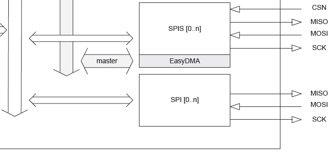
    As far as I know, if you use the NRF51822 as a master, you might need to control the CS pin to low manually.

    (Since I haven't tried SPI, I state my answer with caution.)

    But you did not make a connection with the CS pin, did you?

    Block

    Assuming the code is correct, I really hope it is just a soldering problem.

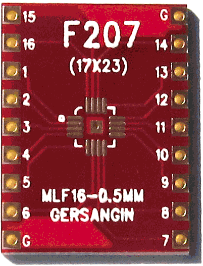
    Also I will just assume that you have soldered the accelerometer to a board like this.

    Change

    I don't know what this is called in English.

    So, can you check two things?

    1. If you have an oscilloscope, can you check your CS pin drops to 0 Volts when you read?

    If it does not become low, the accelerometer is using I2C.

    Read

    i2c

    1. What is the result when you read the WHO_AM_I (0Fh) register?

    The result should be 0x33.

    Who Am I

    If you do not receive this, the soldering may not be done perfectly to that red board up there.

    Finally, try your code once more after adding codes about lowering the CS.

    Or ask the Nordic developers whether the SDK can control the CS pin you are about to use.

    I hope you could search some examples that lowers the CS pins.

    Also, check once more about theSPI_MODE0 ,1 ,2 ,or 3 you should use.

    -Regards, Mango922

  • I'm not 100% sure whether it is okay to hold the CS pin to GND.

    The best way to check is using the oscilloscope, in my opinion.

    Because you can tell whether your code is wrong or your hardware has problems.

    Hook up the MISO and MOSI if they show the result you expected.

    If it does not, it won't be good to hold the CS pin to GND.

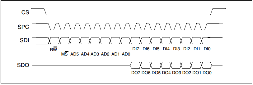
    As you see at the datasheet, Figure 10 shows that you need to tie the CS to GND to write multiple bytes.

    However, your code may not create the clock signal continuously like Figure 10.

    Also, if you see Figure 3, CS's hold time and Output disable time are stated.

    You have to make the signals like Figure 3 and I think holding the CS to GND will screw this.

    In this sense, I do not recommend you to tie the CS pin.

    I hope for you to work out well.

Reply
  • I'm not 100% sure whether it is okay to hold the CS pin to GND.

    The best way to check is using the oscilloscope, in my opinion.

    Because you can tell whether your code is wrong or your hardware has problems.

    Hook up the MISO and MOSI if they show the result you expected.

    If it does not, it won't be good to hold the CS pin to GND.

    As you see at the datasheet, Figure 10 shows that you need to tie the CS to GND to write multiple bytes.

    However, your code may not create the clock signal continuously like Figure 10.

    Also, if you see Figure 3, CS's hold time and Output disable time are stated.

    You have to make the signals like Figure 3 and I think holding the CS to GND will screw this.

    In this sense, I do not recommend you to tie the CS pin.

    I hope for you to work out well.

Children
No Data
Related