NCS 1.8 direction_finding_connectionless_rx AoA can't work

aoa rx hardware: nrf52833DK

aoa tx hardware: my test nrf52833 board

my test nrf52833 board download "direction_finding_connectionless_tx", use "overlay-aoa.conf"

nrf52833DK download "direction_finding_connectionless_rx", not use "gpio 1/2/3/4", like these:

    dfegpio0-gpios = <&gpio0 29 0>;
    dfegpio1-gpios = <&gpio0 28 0>;
    dfegpio2-gpios = <&gpio0 4 0>;
    dfegpio3-gpios = <&gpio0 3 0>;
rx uart output like this:

[16:11:04.122]收←◆PER_ADV_SYNC[0]: [DEVICE]: 01:CE:17:98:2F:00 (random), tx_power 127, RSSI -127, CTE AOA, data length 0, data: 
CTE[0]: samples count 45, cte type AOA, slot durations: 2 [us], packet status CRC OK, RSSI -1270
PER_ADV_SYNC[0]: [DEVICE]: 01:CE:17:98:2F:00 (random), tx_power 127, RSSI -33, CTE AOA, data length 0, data: 
CTE[0]: samples count 45, cte type AOA, slot durations: 2 [us], packet status CRC OK, RSSI -330
PER_ADV_SYNC[0]: [DEVICE]: 01:CE:17:98:2F:00 (random), tx_power 127, RSSI -33, CTE AOA, data length 0, data: 
CTE[0]: samples count 45, cte type AOA, slot durations: 2 [us], packet status CRC OK, RSSI -330
PER_ADV_SYNC[0]: [DEVICE]: 01:CE:17:98:2F:00 (random), tx_power 127, RSSI -33, CTE AOA, data length 0, data: 
CTE[0]: samples count 45, cte type AOA, slot durations: 2 [us], packet status CRC OK, RSSI -330
PER_ADV_SYNC[0]: [DEVICE]: 01:CE:17:98:2F:00 (random), tx_power 127, RSSI -33, CTE AOA, data length 0, data: 
CTE[0]: samples count 45, cte type AOA, slot durations: 2 [us], packet status CRC OK, RSSI -330

[16:11:06.522]收←◆PER_ADV_SYNC[0]: [DEVICE]: 01:CE:17:98:2F:00 (random), tx_power 127, RSSI -127, CTE AOA, data length 0, data: 
CTE[0]: samples count 45, cte type AOA, slot durations: 2 [us], packet status CRC OK, RSSI -1270
PER_ADV_SYNC[0]: [DEVICE]: 01:CE:17:98:2F:00 (random), tx_power 127, RSSI -33, CTE AOA, data length 0, data: 
CTE[0]: samples count 45, cte type AOA, slot durations: 2 [us], packet status CRC OK, RSSI -330
PER_ADV_SYNC[0]: [DEVICE]: 01:CE:17:98:2F:00 (random), tx_power 127, RSSI -33, CTE AOA, data length 0, data: 
CTE[0]: samples count 45, cte type AOA, slot durations: 2 [us], packet status CRC OK, RSSI -330
PER_ADV_SYNC[0]: [DEVICE]: 01:CE:17:98:2F:00 (random), tx_power 127, RSSI -33, CTE AOA, data length 0, data: 
CTE[0]: samples count 45, cte type AOA, slot durations: 2 [us], packet status CRC OK, RSSI -330
PER_ADV_SYNC[0]: [DEVICE]: 01:CE:17:98:2F:00 (random), tx_power 127, RSSI -33, CTE AOA, data length 0, data: 
CTE[0]: samples count 45, cte type AOA, slot durations: 2 [us], packet status CRC OK, RSSI -330

Question:

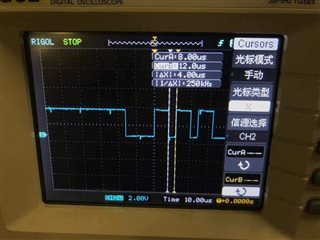
    I use oscilloscope, find gpio29=H, gpio28/4/3=L,  because  dfe-pdu-antenna = <0x1>, but oscilloscope can't find gpio change like  ant_patterns[] = { 0x1, 0x2, 0x3, 0x4, 0x50x6, 0x7, 0x8, 0x9, 0xA }, why? 

    when set dfe-pdu-antenna = <0x6>,  oscilloscope finds gpio29/3=L, gpio28/4=H, also oscilloscope can't find gpio3/4/28/29 change.

thanks.

Parents
  • I can find that by default the gpios used are \v1.8.0\nrf\samples\bluetooth\direction_finding_connectionless_tx\boards\nrf52833dk_nrf52833.overlay

    /*
     * Copyright (c) 2021 Nordic Semiconductor ASA
     *
     * SPDX-License-Identifier: LicenseRef-Nordic-5-Clause
     */
    
    &radio {
    	status = "okay";
    	/* This is a number of antennas that are available on antenna matrix
    	 * designed by Nordic. For more information see README.rst.
    	 */
    	dfe-antenna-num = <12>;
    	/* This is a setting that enables antenna 12 (in antenna matrix designed
    	 * by Nordic) for Tx PDU. For more information see README.rst.
    	 */
    	dfe-pdu-antenna = <0x0>;
    
    	/* These are GPIO pin numbers that are provided to
    	 * Radio peripheral. The pins will be acquired by Radio to
    	 * drive antenna switching when AoD is enabled.
    	 * Pin numbers are selected to drive switches on antenna matrix
    	 * desinged by Nordic. For more information see README.rst.
    	 */
    	dfegpio0-gpios = <&gpio0 3 0>;
    	dfegpio1-gpios = <&gpio0 4 0>;
    	dfegpio2-gpios = <&gpio0 28 0>;
    	dfegpio3-gpios = <&gpio0 29 0>;
    };

    If you find that changing any of these pins are not reflected, then it is likely that the pins in question may for instance be used by uart, i2c, spi or other peripheral.

Reply
  • I can find that by default the gpios used are \v1.8.0\nrf\samples\bluetooth\direction_finding_connectionless_tx\boards\nrf52833dk_nrf52833.overlay

    /*
     * Copyright (c) 2021 Nordic Semiconductor ASA
     *
     * SPDX-License-Identifier: LicenseRef-Nordic-5-Clause
     */
    
    &radio {
    	status = "okay";
    	/* This is a number of antennas that are available on antenna matrix
    	 * designed by Nordic. For more information see README.rst.
    	 */
    	dfe-antenna-num = <12>;
    	/* This is a setting that enables antenna 12 (in antenna matrix designed
    	 * by Nordic) for Tx PDU. For more information see README.rst.
    	 */
    	dfe-pdu-antenna = <0x0>;
    
    	/* These are GPIO pin numbers that are provided to
    	 * Radio peripheral. The pins will be acquired by Radio to
    	 * drive antenna switching when AoD is enabled.
    	 * Pin numbers are selected to drive switches on antenna matrix
    	 * desinged by Nordic. For more information see README.rst.
    	 */
    	dfegpio0-gpios = <&gpio0 3 0>;
    	dfegpio1-gpios = <&gpio0 4 0>;
    	dfegpio2-gpios = <&gpio0 28 0>;
    	dfegpio3-gpios = <&gpio0 29 0>;
    };

    If you find that changing any of these pins are not reflected, then it is likely that the pins in question may for instance be used by uart, i2c, spi or other peripheral.

Children
  • thanks

    I get some questions:

    1.

        but I use pin 3/4/28/29 as general GPIO (codes as below), the pins can toggle( the LED2 can pin 3/4/28/29).

    void blink2(void)
    {
    	int ret;
    
    	led2_dev = device_get_binding(LED2);
    	if (led2_dev == NULL) {
    		return;
    	}
    	ret = gpio_pin_configure(led2_dev, LED2_PIN, GPIO_OUTPUT_ACTIVE | LED2_FLAGS);
    	if (ret < 0) {
    		return;
    	}
    	//off led
    	gpio_pin_set(led2_dev, LED2_PIN, false);
    
    	while (1) {
    		k_msleep(300);
    		gpio_pin_toggle(led2_dev, LED2_PIN);
    	}
    }

    so  I think 3/4/28/29  may  NOT for instance be used by uart, i2c, spi or other peripheral.

    2.

    In my project  default "dfe-antenna-num = <10>;"  not as you mentioned "dfe-antenna-num = <12>;"  are you NCS 1.8.0 or not?

    3.

    I use project "\v1.8.0\zephyr\samples\bluetooth\direction_finding_connectionless_tx", not as you describled "\v1.8.0\nrf\samples\bluetooth\direction_finding_connectionless_tx", am I wrong?

    thanks, again.

  • Please use the project in the \nrf\ folder, all new development and features are done on the \nrf\ folder. So you should use the \nrf\ project for development.

    The project in the \zephyr\ are mainly there for CI testing upstrem in zephyr, to ensure no changes are occuring that may break development.

    Best regards,
    Kenneth

  • thank you very much. I get the waves like this:

    the slot is 2us.

    BUT, waves may disappear sometimes, then I reboot aoa rx board, the oscilloscope  can get the waves, the aoa rx sample may have a bug?

    thanks.

Related