What is the output impedance of the ANT1 antenna pin on the NRF52833-QIAA

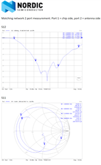
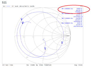
We are designing a custom antenna for the nrf52833-QIAA.  Could you supply the output impedance of the ANT1 antenna pin so that we can run an HFSS simulation on our layout and matching network for our custom antenna?  This post

https://devzone.nordicsemi.com/f/nordic-q-a/21777/nrf52832-ant-pin-impedance#:~:text=the%20load%20impedance%20of%20the,should%20be%2053%20%2B%20j66%20Ohms

shows the desired load impedance of the nRF52832CIAA antenna pin as 53+j66, but I haven't found numbers for the nrf52833-QIAA.

Thanks,

Isaac Davenport

Parents
  • I should clarify, I am looking for the output impedance of the ANT pin output.  ANT1 is the net name we had on our own schematic since we have more than one chip with an ANT pin.  Additionally I found a support page listing the output impedance of the nrf52840 as: .  https://devzone.nordicsemi.com/f/nordic-q-a/26733/what-is-the-input-impedance-of-nrf52840-in-different-modes 

    "The output impedance of the ANT pin of the nRF52840 at TX power of 0dBm is 115.771 + 33.357j ohms"

    I suspect that impedance is closer to the nrf52833, but I would really like the actual impedance number for our chip, the 52833, assuming you have it.

  • Hi Isaac,

    The radio front end is identical on the nRF52833 and nRF52840, so I'm pretty sure you can use the impedance for the nRF52840, but I will double check tomorrow and get back to you.

    Best regards,

    Martin S.

  • Thanks.  It looks like it depends on the package, QIAA in our case, as well as the output power.  I think we would want to optimize for the impedance at +4dB to maximize your ultimate range.

  • Hi Isaac,

    I checked with a colleague that has done direct measurements, and says that 115.771 + 33.357j ohms isn't correct.

    He also said that we can't say anything about the output impedance of the ANT pin, that it doesn't make sense, but what we can say something about is what load impedance is preferred seen into the matching network, and has measured that to be 35 -j46 ohm.

    I can also copy this from a previous case with the same question:

    If you want to design a matching network optimal for max 0 dBm output power, you can get away with just a shunt capacitor and a series inductor. Provided you ground the shunt capacitor like in the reference layout. A 0.8 pF capacitor and 3.9 nH inductor is a good starting point. Measure the impedance seen into the matching network with the radio in TX mode and adjust for 50 ohm.

    The additional components are needed to filter harmonics in 4 and 8 dBm mode.

    The radio front end is identical on the nRF52833 and nRF52840. The reason for the extra inductor in the nRF52833 matching network is to have more margins for the harmonics to the radio regulatory limits in 8 dBm mode. 

    Both the -833 and -840 matching networks are ok in 8 dBm mode, it's just that we wanted to attenuate the harmonics a bit more. If you only use 0 and 4 dBm, you can use the -840 matching network on both devices.

    Best regards,

    Martin S.

Reply
  • Hi Isaac,

    I checked with a colleague that has done direct measurements, and says that 115.771 + 33.357j ohms isn't correct.

    He also said that we can't say anything about the output impedance of the ANT pin, that it doesn't make sense, but what we can say something about is what load impedance is preferred seen into the matching network, and has measured that to be 35 -j46 ohm.

    I can also copy this from a previous case with the same question:

    If you want to design a matching network optimal for max 0 dBm output power, you can get away with just a shunt capacitor and a series inductor. Provided you ground the shunt capacitor like in the reference layout. A 0.8 pF capacitor and 3.9 nH inductor is a good starting point. Measure the impedance seen into the matching network with the radio in TX mode and adjust for 50 ohm.

    The additional components are needed to filter harmonics in 4 and 8 dBm mode.

    The radio front end is identical on the nRF52833 and nRF52840. The reason for the extra inductor in the nRF52833 matching network is to have more margins for the harmonics to the radio regulatory limits in 8 dBm mode. 

    Both the -833 and -840 matching networks are ok in 8 dBm mode, it's just that we wanted to attenuate the harmonics a bit more. If you only use 0 and 4 dBm, you can use the -840 matching network on both devices.

    Best regards,

    Martin S.

Children
No Data
Related