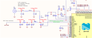
I am tying to match the nRF52840 rf output to my 50 ohm 2.45GHz pcb antenna. What is the optimum rf impedance for best transmitter/receiver performance? The markings on the chip are N52840 QIAAC0 1908GK.
Thankyou,
Doug
I am tying to match the nRF52840 rf output to my 50 ohm 2.45GHz pcb antenna. What is the optimum rf impedance for best transmitter/receiver performance? The markings on the chip are N52840 QIAAC0 1908GK.
Thankyou,
Doug
Hi Martin,
I am going to first make adjustments to the pcb antenna geometry to get it to 50 ohms. Here is the schematic (this was not done by me, I am trying to verify/improve it). I can provide trace widths and pcb stackup later. The problem is how will I ever know if I have this right without doing radiated measurements? I am an experienced rf design engineer with a Vector Network Analyzer, simulation tools, and the know-how to design my own matching circuit. If I knew the PA output impedance I could design the match/filter and verify it with a VNA.
