This discussion has been locked.
You can no longer post new replies to this discussion. If you have a question you can start a new discussion

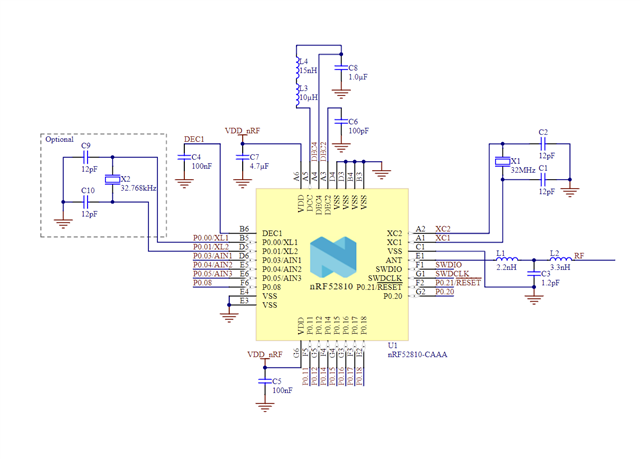
Absolute minimum for 4.7uF VDD decoupling capacitor on nRF52810-CAAA (WLCSP package, C8 in reference schematic)

Hello, I am developing a custom board using the nRF52810 WLCSP package. I realized I made an error in the board layout after placing my order, the error being that I placed a 1.0uF 01005 capacitor at C8 where a 4.7uF capacitor should be. Since I had the board fabbed with an 01005 footprint, I cannot swap/place a 4.7uF capacitor here without some very tedious and tricky soldering work (4.7uF only offered in 0201 and larger packages, and the 01005 footprint I used has very small pad tolerance so any other size will not fit). 

I understand that this capacitor is on the VDD bus by the radio, which is why the reference schematic lists 4.7uF and not 100nF. I am advertising with TX power set to +4 dBm. What kind of impact will a 1.0uF capacitor have compared to the recommended 4.7uF capacitor? Is this a significant enough error to render my antenna "useless" or should I still expect to see BLE signal? 

Thanks!

Parents
  • Hi Noah

    I assume you mean C7 as C8 is already 1.0 µF? 

    It's not critical that it's 4.7 µF. But you need at least one large cap on the net. 1.0 µF is ok here. It's mainly to avoid too large voltage drops when the radio starts. 

    If it doesn't work, it's not that.

    best regards,

    Ketil Aas-Johansen

Reply
  • Hi Noah

    I assume you mean C7 as C8 is already 1.0 µF? 

    It's not critical that it's 4.7 µF. But you need at least one large cap on the net. 1.0 µF is ok here. It's mainly to avoid too large voltage drops when the radio starts. 

    If it doesn't work, it's not that.

    best regards,

    Ketil Aas-Johansen

Children
No Data
Related