Hello Devzone,
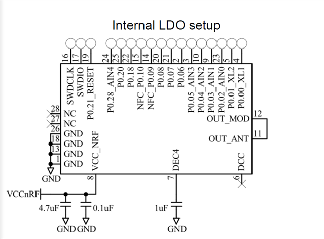
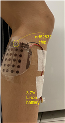
Our research group is using the NRF52832 chip embedded in a flexible substrate to transmit EMG (muscle) signals via Bluetooth. We’ve been having a couple issues with our device and have isolated two issues to the NRF chip. For some background, here is a picture of the device placed on a user’s calf muscle. The NRF chip is connected to an ADC chip that measures potentials and serially sends each electrode’s potential as a 16-bit integer. Each packet is sent as a Notification, so the device shouldn’t expect an acknowledgement from the central device.
- Device disconnects unexpectedly only when flexing
Our device attempts to send 12800 bytes per second (0.0128 Mb/s) and does so smoothly until the user starts flexing. It first starts sending packets at a slower rate, but sometimes shuts down entirely. I read from this website (https://www.novelbits.io/bluetooth-5-speed-maximum-throughput/) that the maximum throughput for a Bluetooth 5.0 device is 1.434 Mb/s. This sampling rate is also within the ADC chip’s limit of 1.05Ms per second (we sample at 32000 samples/second). The random disconnection happens with Android and Bluetooth devices (using the NRF connect app). I have not tried using the an NRF development board to connect to the device, but I will try that soon.
It seems that the device is struggling to send data at less than around 1/100 the expected bandwidth.
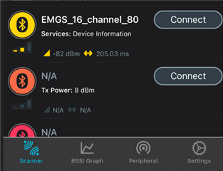
I think one reason may be the low transmitting power of the sEMG, which is consistently at -70 to -85 dBm a couple feet away from the BLE device. There is no backplane for the NRF chip which explains the low transmitting power.
Either way, we have observed that a larger sampling rate causes the device to disconnect and shut down sooner. Would you all have any solutions to this issue?
- NRF chip draws too much current when powered
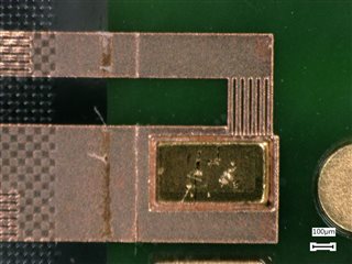
We use a probe station to connect to the VDD, GND, SDIO, and SDCLK pins on the sEMG whenever it needs to be reprogrammed (shown in the picture below).

After being reprogrammed 3-4 times, the device starts to draw much more current than listed in the spec sheet. When under a supply voltage of 3.3V with a current limit of 14 mA, the device draws the maximum current when it should be drawing 8-9 mA. This is affecting our ability to reprogram the samples and might also contribute the the issue of the device disconnecting unexpectedly.
I thought that probing may have caused a short in the device, but the resistance between the VDD and GND pads are on the order of kOhms, and the resistance of the the other IO and CLK pads to VDD or GND are on the order of MOhms.
Here is the picture of the power supply when we powered the device – supply 1 has to limit the output voltage to 2.698 to limit the current despite being set to 3.3V.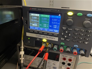
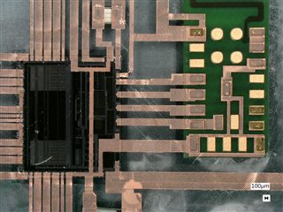
Also, here is a picture taken of the NRF chip and its connected ADC chip, as well as the closeup of the most damaged pin (VDD) – we didn’t see anything unusual here, but if there is anything that catches your eye, please let us know?
Any suggestions on how to identify the issue would be greatly appreciated – for now I am using a program with low data throughput to prevent the disconnects from happening and using a newer device (since the performance seems to degrade over time).
Thank you for your time!
Pragathi Venkatesh
UCLA CHIPS Lab