First, NRF52833 work environment at 100 degrees celsius, standby current reaches 60uA.
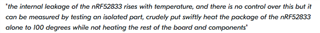
Second, When the NRF52833 working in 100 degrees Celsius, what kind of processing software or hardware needs to be done.
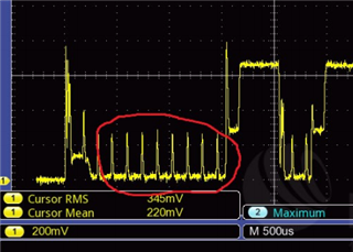
Third, When the NRF52833 dormant, how to shielding the red signal in the frame? As is shown.