Dear All.
I tried to test and evaluate LoRaWAN stack on Zephyr, without success. I will need more time to debug what is happening by the logic analyzer. Meantime I attached the configurations to confirm, if anybody tried the same.
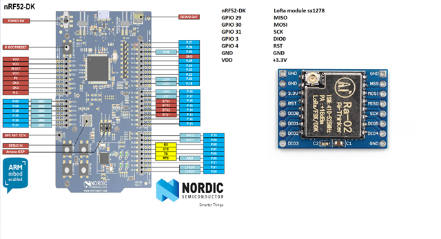
SX1276MB1LAS + nrf52832-DK:
&spi0 {
compatible = "nordic,nrf-spi";
status = "okay";
mosi-pin = <23>;
miso-pin = <24>;
sck-pin = <25>;
cs-gpios = <&gpio0 22 GPIO_ACTIVE_LOW>;
miso-pull-up;
lora0: sx1276@0 {
compatible = "semtech,sx1276";
reset-gpios = <&gpio0 3 GPIO_ACTIVE_LOW>;
dio-gpios = <&gpio0 13 GPIO_ACTIVE_HIGH>,
<&gpio0 14 GPIO_ACTIVE_HIGH>,
<&gpio0 15 GPIO_ACTIVE_HIGH>,
<&gpio0 16 GPIO_ACTIVE_HIGH>,
<&gpio0 19 GPIO_ACTIVE_HIGH>,
<&gpio0 20 GPIO_ACTIVE_HIGH>;
//antenna-enable-gpios = <&gpio0 30 GPIO_ACTIVE_HIGH>;
power-amplifier-output = "pa-boost";
reg = <0>;
spi-max-frequency = <1000000>;
label = "SX1276";
};
};
SX1262MB2CAS + nrf52832-DK:
&spi0 {
compatible = "nordic,nrf-spi";
status = "okay";
miso-pin = <24>;
mosi-pin = <23>;
sck-pin = <25>;
cs-gpios = <&gpio0 18 GPIO_ACTIVE_LOW>;
miso-pull-up;
lora0: sx1262@0 {
compatible = "semtech,sx1262";
reg = <0>;
label = "sx1262";
reset-gpios = <&gpio0 3 GPIO_ACTIVE_LOW>;
antenna-enable-gpios = <&gpio0 19 GPIO_ACTIVE_LOW>;
busy-gpios = <&gpio0 14 GPIO_ACTIVE_HIGH>;
dio1-gpios = <&gpio0 16 GPIO_ACTIVE_HIGH>;
spi-max-frequency = <1000000>;
};
};
# enable SPI
CONFIG_SPI=y
CONFIG_SPI_NRFX=y
# Enable the SX12XX radio driver for Lora
CONFIG_LORA=y
CONFIG_LORA_LOG_LEVEL_DBG=y
CONFIG_LORA_SX12XX=y
CONFIG_LORA_SX127X=y
# Enable the Lorawan stack
CONFIG_LORAWAN=y
CONFIG_LORAWAN_LOG_LEVEL_DBG=y
CONFIG_HAS_SEMTECH_LORAMAC=y
CONFIG_HAS_SEMTECH_SOFT_SE=y
CONFIG_HAS_SEMTECH_RADIO_DRIVERS=y
# Define the Lorawan region to be used
CONFIG_LORAMAC_REGION_AU915=y
#CONFIG_LORAMAC_REGION_US915=y
#CONFIG_LORAWAN_SYSTEM_MAX_RX_ERROR=90
seems that it is not transmitting anything...
00> [00:00:00.271,942] <dbg> sx126x.sx126x_lora_init: Initializing sx1262
00> [00:00:00.272,033] <dbg> sx126x.SX126xReset: Resetting radio
00> [00:00:00.302,398] <dbg> sx126x.SX126xIoIrqInit: Configuring DIO IRQ callback
00> [00:00:00.302,520] <dbg> sx126x.SX126xWakeup: Sending GET_STATUS
00> [00:00:00.302,703] <dbg> sx126x.SX126xWakeup: Waiting for device...
00> [00:00:00.302,703] <dbg> sx126x.SX126xWakeup: Device ready
00> [00:00:00.302,734] <dbg> sx126x.SX126xWriteCommand: Issuing opcode 0x80 w. 1 bytes of data
00> [00:00:00.302,947] <dbg> sx126x.SX126xSetOperatingMode: SetOperatingMode: STDBY_RC (1)
00> [00:00:00.302,947] <dbg> sx126x.SX126xIoTcxoInit: No TCXO configured
00> [00:00:00.302,978] <dbg> sx126x.SX126xIoRfSwitchInit: Configuring DIO2
00> [00:00:00.302,978] <dbg> sx126x.SX126xWriteCommand: Issuing opcode 0x9d w. 1 bytes of data
00> [00:00:00.303,192] <dbg> sx126x.SX126xSetOperatingMode: SetOperatingMode: STDBY_RC (1)
00> [00:00:00.303,19
00> [00:00:05.719,268] <dbg> sx126x.SX126xWriteCommand: Issuing opcode 0x80 w. 1 bytes of data
00> [00:00:05.719,390] <dbg> sx126x.SX126xWakeup: Sending GET_STATUS
00> [00:00:05.719,543] <dbg> sx126x.SX126xWakeup: Waiting for device...
00> [00:00:05.720,703] <dbg> sx126x.SX126xWakeup: Device ready
00> [00:00:05.720,703] <dbg> sx126x.SX126xAntSwOn: Enabling antenna switch
00> [00:00:05.720,916] <dbg> sx126x.SX126xSetOperatingMode: SetOperatingMode: STDBY_RC (1)
00> [00:00:05.720,947] <dbg> sx126x.SX126xWriteCommand: Issuing opcode 0x86 w. 4 bytes of data
00> [00:00:05.722,351] <dbg> sx126x.SX126xWriteCommand: Issuing opcode 0x9f w. 1 bytes of data
00> [00:00:05.722,564] <dbg> sx126x.SX126xWriteCommand: Issuing opcode 0x80 w. 1 bytes of data
00> [00:00:05.722,778] <dbg> sx126x.SX126xSetOperatingMode: SetOperatingMode: STDBY_RC (1)
00> [00:00:05.722,808] <dbg> sx126x.SX126xWriteCommand: Issuing opcode 0x8a w. 1 bytes of data
00> [00:00:05.723,052] <dbg> sx126x.SX126xWriteCommand: Issuing opcode 0x8b w. 4 bytes of data
00> [00:00:05.724,426] <dbg> sx1[00:00:05.725,402] <dbg> sx126x.SX126xWriteRegisters: Writing 1 registers @ 0x736: 0x9 , ...
00> [00:00:05.725,646] <dbg> sx126x.SX126xWriteCommand: Issuing opcode 0x8c w. 6 bytes of data
00> [00:00:05.725,891] <dbg> sx126x.SX126xWriteCommand: Issuing opcode 0x8 w. 8 bytes of data
00> [00:00:05.726,165] <dbg> sx126x.SX126xSetOperatingMode: SetOperatingMode: RX (5)
00> [00:00:05.726,196] <dbg> sx126x.SX126xWriteRegisters: Writing 1 registers @ 0x8ac: 0x94 , ...
00> [00:00:05.726,440] <dbg> sx126x.SX126xWriteCommand: Issuing opcode 0x82 w. 3 bytes of data
00> [00:00:05.775,939] <dbg> sx126x.sx126x_dio1_irq_work_handler: Processing DIO1 interrupt
00> [00:00:05.776,000] <dbg> sx126x.SX126xReadCommand: Issuing opcode 0x12 (data size: 2)
00> [00:00:05.776,214] <dbg> sx126x.SX126xReadCommand: -> status: 0xa6
00> [00:00:05.776,245] <dbg> sx126x.SX126xWriteCommand: Issuing opcode 0x2 w. 2 bytes of data
00> [00:00:05.776,458] <dbg> sx126x.SX126xSetOperatingMode: SetOperatingMode: STDBY_RC (1)
00> [00:00:05.776,489] <dbg> sx126x.SX126xAntSwOff: Disabling antenna switch
00> [00:00:05.776,489] <dbg> sx126x.SX126xWriteCommand: Issuing opcode 0x84 w. 1 bytes of data
00> [00:00:05.776,702] <dbg> sx126x.SX126xSetOperatingMode: SetOperatingMode: SLEEP (0)
00> [00:00:06.739,990] <dbg> sx126x.SX126xWriteCommand: Issuing opcode 0x80 w. 1 bytes of data
00> [00:00:06.740,051] <dbg> sx126x.SX126xWakeup: Sending GET_STATUS
00> [00:00:06.740,173] <dbg> sx126x.SX126xWakeup: Waiting for device...
00> [00:00:06.741,363] <dbg> sx126x.SX126xWakeup: Device ready
00> [00:00:06.741,394] <dbg> sx126x.SX126xAntSwOn: Enabling antenna switch
00> [00:00:06.741,607] <dbg> sx126x.SX126xSetOperatingMode: SetO0m
00> [00:00:06.743,011] <dbg> sx126x.SX126xWriteCommand: Issuing opcode 0x9f w. 1 bytes of data
00> [00:00:06.743,255] <dbg> sx126x.SX126xWriteCommand: Issuing opcode 0x80 w. 1 bytes of data
00> [00:00:06.743,469] <dbg> sx126x.SX126xSetOperatingMode: SetOperatingMode: STDBY_RC (1)
00> [00:00:06.743,469] <dbg> sx126x.SX126xWriteCommand: Issuing opcode 0x8a w. 1 bytes of data
00> [00:00:06.743,682] <dbg> sx126x.SX126xWriteCommand: Issuing opcode 0x8b w. 4 bytes of data
00> [00:00:06.745,086] <dbg> sx126x.SX126xWriteCommand: Issuing opcode 0x8c w. 6 bytes of data
00> [00:00:06.745,360m
00> [00:00:06.745,574] <dbg> sx126x.SX126xWriteRegisters: Writing 1 registers @ 0x706: 0x28 , ...
00> [00:00:06.745,819] <dbg> sx126x.SX126xReadRegisters: Reading 1 registers @ 0x736
00> [00:00:06.746,032] <dbg> sx126x: register_value
00> 0d |.
00> [00:00:06.746,063] <dbg> sx126x.SX126xWriteRegisters: Writing 1 registers @ 0x736: 0x9 , ...
00> [00:00:06.746,307] <dbg> sx126x.SX126xWriteCommand: Issuing opcode 0x8c w. 6 bytes of data
00> [00:00:06.746,551] <dbg> sx126x.SX126xWriteCommand: Issuing opcode 0x8 w. 8 bytes of data
00> [00:00:06.746,917] <dbg> sx126x.SX126xSetOperatingMode: SetOperatingMode: RX (5)
00> [00:00:06.746,948] <dbg> sx126x.SX126xWriteRegisters: Writing 1 registers @ 0x8ac: 0x94 , ...
00> [00:00:06.747,161] <dbg> sx126x.SX126xWriteCommand: Issuing opcode 0x82 w. 3 bytes of data
00> [00:00:06.829,437] <dbg> sx126x.sx126x_dio1_irq_work_handler: Processing DIO1 interrupt
00> [00:00:06.829,528] <dbg> sx126x.SX126xReadCommand: Issuing opcode 0x12 (data size: 2)
00> [00:00:06.829,742] <dbg> sx126x.SX126xReadCommand: -> status: 0xa6
00> [00:00:06.829,772] <dbg> sx126x.SX126xWriteCommand: Issuing opcode 0x2 w. 2 bytes of data
00> [00:00:06.830,017] <dbg> sx126x.SX126xSetOperatingMode: SetOperatingMode: STDBY_RC (1)
00> [00:00:06.830,017] <dbg> sx126x.SX126xAntSwOff: Disabling antenna switch
00> [00:00:06.830,047] <dbg> sx126x.SX126xWriteCommand: Issuing opcode 0x84 w. 1 bytes of data
00> [00:00:06.830,261] <dbg> sx126x.SX126xSetOperatingMode: SetOperatingMode: SLEEP (0)
00> [00:00:06.832,458] <dbg> lorawan.MlmeConfirm: Received MlmeConfirm (for MlmeRequest 1)
00> [00:00:06.832,489] <err> lorawan: MlmeConfirm failed : Rx 2 timeout
00> [00:00:06.835,357] <err> lorawan_class_a: lorawan_join_network failed: -116
Thanks in advance...