
Dear community
I am developing an autarkic embedded system where I harvest energy from a thermoelectrical generator. It is a simple application, I need to acquire the open circuit voltage of the TEG to determine the temperature difference and send it over BLE to a smartphone. As a boost converter I am using the MCRY12-125Q-DI from Matrix Industries which offers an interface to read out the open circuit voltage of the thermoelectric generator. This interface simplifies the programm, since it doesnt need an ADC.
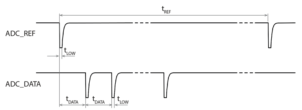
The signals from the MCRY12 boost converter look like in following picture. tRef is 51ms, tData = 200us, tLow = 10ns. Every pulse in ADC_Data counts for 2mV open circuit voltage. To obtain the open circuit voltage, I only need to read the ADC_DATA pulses between two ADC_REF pulses.
I am using the GPIOTE to trigger interrupts at from the ADC_REF and ADC_DATA pins: The measurement starts when a first ADC_REF signal is received, then it counts the pulses at the ADC_DATA pin until a 2nd ADC_REF pulse is measured. This open circuit voltage is stored into an array and read when its needed. The measurement will be started in start_measuring_teg_voltage() and is called every 10s.
/** @example App_GPIOTE.c
 *
 * @brief ADC implementation for the lactate measurements
 *
 * This file contains the source for the ADC conversion for the lactate measurements
 */

#include "App_GPIOTE.h"

#define 					PIN_ADC_REF					(14)		// P13
#define 					PIN_ADC_DATA				(14+2)	// P14

static bool				measuring = false;
static uint16_t		edges_counter = 0;

static uint16_t		temperature_cnt = 0;
uint8_t						temperature_gpiote[TEMPERATURE_LENGTH];

void in_adc_meas_ref_handler(nrf_drv_gpiote_pin_t pin, nrf_gpiote_polarity_t action)
{
		// Measuring started
		if(action == NRF_GPIOTE_POLARITY_HITOLO && !measuring && pin == PIN_ADC_REF)
		{
				measuring = true;
				edges_counter = 0;

				nrf_drv_gpiote_in_event_enable(PIN_ADC_DATA, true);
				nrf_drv_gpiote_in_event_enable(PIN_ADC_REF, true);
		}

		// Measurement finished
		else if(action == NRF_GPIOTE_POLARITY_HITOLO && measuring && pin == PIN_ADC_REF)
		{
				nrf_drv_gpiote_in_event_disable(PIN_ADC_DATA);
				nrf_drv_gpiote_in_event_disable(PIN_ADC_REF);
				measuring = false;
				edges_counter *= 2;		// 1 Tick = 2mV
				temperature_gpiote[temperature_cnt] = edges_counter; // voltage in millivolt
				temperature_cnt++;
		}
}

void in_adc_meas_data_handler(nrf_drv_gpiote_pin_t pin, nrf_gpiote_polarity_t action)
{
		// Counter data pulses
		if(action == NRF_GPIOTE_POLARITY_HITOLO && measuring && pin == PIN_ADC_DATA)
		{
				edges_counter++;
				nrf_drv_gpiote_in_event_enable(PIN_ADC_DATA, true);
		}
}

void gpio_init(void)
{
		if(!nrf_drv_gpiote_is_init())
		{
				ret_code_t err_code;

				err_code = nrf_drv_gpiote_init();
				APP_ERROR_CHECK(err_code);

				nrf_drv_gpiote_in_config_t in_ref_config = GPIOTE_CONFIG_IN_SENSE_HITOLO(false);
				in_ref_config.pull = NRF_GPIO_PIN_PULLUP;

				err_code = nrf_drv_gpiote_in_init(PIN_ADC_REF, &in_ref_config, in_adc_meas_ref_handler);
				APP_ERROR_CHECK(err_code);

				nrf_drv_gpiote_in_config_t in_data_config = GPIOTE_CONFIG_IN_SENSE_HITOLO(false);
				in_data_config.pull = NRF_GPIO_PIN_PULLUP;

				err_code = nrf_drv_gpiote_in_init(PIN_ADC_DATA, &in_data_config, in_adc_meas_data_handler);
				APP_ERROR_CHECK(err_code);

				nrf_drv_gpiote_in_event_disable(PIN_ADC_REF);
				nrf_drv_gpiote_in_event_disable(PIN_ADC_DATA);

		}
}


void start_measuring_teg_voltage(void)
{
		nrf_drv_gpiote_in_event_enable(PIN_ADC_REF, true);
		//nrf_drv_gpiote_in_event_enable(PIN_ADC_DATA, true);
		//nrf_drv_gpiote_in_event_disable(PIN_ADC_DATA);
}


uint8_t* get_teg_voltage(void)
{
		temperature_cnt = 0;
		//return &edges_counter; //debug
		return &temperature_gpiote[0];
}
The problem is, that it does not count correct. Edge_counter usually has 0, sometimes 2,3,4 even it should be around 20: I replaced the TEG with a power supply. The signals of the boost converter MCRY12 are correct, I measured them with an oscilloscope.
I am wondering why it does not work. May it be, that 200us is too fast? In my opinion it should work like this. Or dont I see the wood for the trees? :-)
I know this solution is a bit messy and has a lot of potential to improve, also the power consumption might be not ideal, since the MCU wakes up. Meanwhile I try to use the PPI with a timer and GPIOTE like it is described here: GPIOTE and Timer using PPI This solution should consume less power, right?
Best regards
Robert

